
The analysis presented here is based on Bejan’s work (Bejan et al., 1981; Bejan, 1995). The analysis, however, is adapted to imaging collectors, because entropy generation minimization is more important to high-temperature systems. Consider that the collector has an aperture area (or total heliostat area), Aa, and receives solar radiation at the rate Q∗ from the sun, as shown in Figure 3.48. The net solar heat transfer, Q∗, is proportional to the collector area, Aa, and the proportionality factor, q∗ (W/m2), which varies with geographical position on the earth, the orientation of the collector, meteorological conditions, and the time of day. In the present analysis, q∗ is assumed to be constant and the system is in a steady state; that is,
![]() (3.144)
(3.144)
For concentrating systems, q∗ is the solar energy falling on the reflector. To obtain the energy falling on the collector receiver, the tracking mechanism accuracy, the optical errors of the mirror, including its reflectance, and the optical properties of the receiver glazing must be considered.
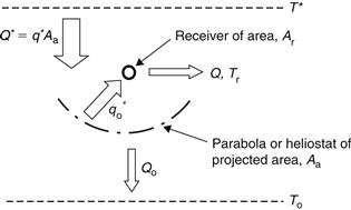
FIGURE 3.48 Imaging concentrating collector model.
Therefore, the radiation falling on the receiver, ![]() , is a function of the optical efficiency, which accounts for all these errors. For the concentrating collectors, Eq. (3.116) can be used. The radiation falling on the receiver is (Kalogirou, 2004):
, is a function of the optical efficiency, which accounts for all these errors. For the concentrating collectors, Eq. (3.116) can be used. The radiation falling on the receiver is (Kalogirou, 2004):
![]() (3.145)
(3.145)
The incident solar radiation is partly delivered to a power cycle (or user) as heat transfer Q at the receiver temperature, Tr. The remaining fraction, Qo, represents the collector-ambient heat loss:
![]() (3.146)
(3.146)
For imaging concentrating collectors, Qo is proportional to the receiver-ambient temperature difference and to the receiver area as:
![]() (3.147)
(3.147)
where Ur is the overall heat transfer coefficient based on Ar. It should be noted that Ur is a characteristic constant of the collector.
Combining Eqs (3.146) and (3.147), it is apparent that the maximum receiver temperature occurs when Q = 0, that is, when the entire solar heat transfer Q∗ is lost to the ambient. The maximum collector temperature is given in dimensionless form by:
Combining Eqs (3.145) and (3.148),
![]() (3.149)
(3.149)
Considering that C = Aa/Ar, then:
![]() (3.150)
(3.150)
As can be seen from Eq. (3.150), θmax is proportional to C, that is, the higher the concentration ratio of the collector, the higher are θmax and Tr,max. The term Tr,max in Eq. (3.148) is also known as the stagnation temperature of the collector, that is, the temperature that can be obtained at a no flow condition. In dimensionless form, the collector temperature, θ = Tr/To, varies between 1 and θmax, depending on the heat delivery rate, Q. The stagnation temperature, θmax, is the parameter that describes the performance of the collector with regard to collector-ambient heat loss, since there is no flow through the collector and all the energy collected is used to raise the temperature of the working fluid to the stagnation temperature, which is fixed at a value corresponding to the energy collected equal to energy loss to ambient. Hence, the collector efficiency is given by:
![]() (3.151)
(3.151)
Therefore ηc is a linear function of collector temperature. At the stagnation point, the heat transfer, Q, carries zero exergy, or zero potential for producing useful work.
3.7.1 Minimum entropy generation rate
The minimization of the entropy generation rate is the same as the maximization of the power output. The process of solar energy collection is accompanied by the generation of entropy upstream of the collector, downstream of the collector, and inside the collector, as shown in Figure 3.49.
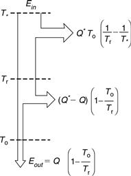
FIGURE 3.49 Exergy flow diagram.
The exergy inflow coming from the solar radiation falling on the collector surface is:
![]() (3.152)
(3.152)
where T∗ is the apparent sun temperature as an exergy source. In this analysis, the value suggested by Petela (1964) is adopted, that is, T∗ is approximately equal to ¾Ts, where Ts is the apparent blackbody temperature of the sun, which is about 5770 K. Therefore, the T∗ considered here is 4330 K. It should be noted that, in this analysis, T∗ is also considered constant; and because its value is much greater than To, Ein is very near Q∗. The output exergy from the collector is given by:
![]() (3.153)
(3.153)
whereas the difference between Ein and Eout represents the destroyed exergy. From Figure 3.49, the entropy generation rate can be written as:
This equation can be written with the help of Eq. (3.146) as:
![]() (3.155)
(3.155)
By using Eqs (3.152) and (3.153), Eq. (3.155) can be written as:
![]() (3.156)
(3.156)
or
![]() (3.157)
(3.157)
Therefore, if we consider Ein constant, the maximization of the exergy output (Eout) is the same as the minimization of the total entropy generation, Sgen.
3.7.2 Optimum collector temperature
By substituting Eqs (3.146) and (3.147) into Eq. (3.155), the rate of entropy generation can be written as:
![]() (3.158)
(3.158)
By applying Eq. (3.150) in Eq. (3.158) and performing various manipulations,
The dimensionless term, Sgen/UrAr, accounts for the fact that the entropy generation rate scales with the finite size of the system, which is described by Ar = Aa/C.
By differentiating Eq. (3.159) with respect to θ and setting it to 0, the optimum collector temperature (θopt) for minimum entropy generation is obtained:
![]() (3.160)
(3.160)
By substituting θmax with Tr,max/To and θopt with Tr,opt/To, Eq. (3.160) can be written as:
![]() (3.161)
(3.161)
This equation states that the optimal collector temperature is the geometric average of the maximum collector (stagnation) temperature and the ambient temperature. Typical stagnation temperatures and the resulting optimum operating temperatures for various types of concentrating collectors are shown in Table 3.4. The stagnation temperatures shown in Table 3.4 are estimated by considering mainly the collector radiation losses.
Table 3.4
Optimum Collector Temperatures for Various Types of Concentrating Collectors
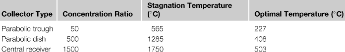
Note: Ambient temperature considered = 25 °C.
As can be seen from the data presented in Table 3.4 for high-performance collectors such as the central receiver, it is better to operate the system at high flow rates to lower the temperature around the value shown instead of operating at very high temperature to obtain higher thermodynamic efficiency from the collector system.
By applying Eq. (3.160) to Eq. (3.159), the corresponding minimum entropy generation rate is:
![]() (3.162)
(3.162)
where θ∗ = T∗/To. It should be noted that, for flat-plate and low-concentration ratio collectors, the last term of Eq. (3.162) is negligible, since θ∗ is much bigger than θmax − 1; but it is not for higher concentration collectors such as the central receiver and the parabolic dish ones, which have stagnation temperatures of several hundreds of degrees.
By applying the stagnation temperatures shown in Table 3.4 to Eq. (3.162), the dimensionless entropy generated against the collector concentration ratios considered here, as shown in Figure 3.50, is obtained.
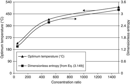
FIGURE 3.50 Entropy generated and optimum temperatures against collector concentration ratio.
3.7.3 Non-isothermal collector
So far, the analysis was carried out considering an isothermal collector. For a non-isothermal one, which is a more realistic model, particularly for long PTCs, and by applying the principle of energy conservation,
![]() (3.163)
(3.163)
where x is from 0 to L (the collector length). The generated entropy can be obtained from:
![]() (3.164)
(3.164)
From an overall energy balance, the total heat loss is:
![]() (3.165)
(3.165)
Substituting Eq. (3.165) into Eq. (3.164) and performing the necessary manipulations, the following relation is obtained:
![]() (3.166)
(3.166)
where θout = Tout/To, θin = Tin/To, Ns is the entropy generation number, and M is the mass flow number given by:
![]() (3.167)
(3.167)
![]() (3.168)
(3.168)
If the inlet temperature is fixed, θin = 1, then the entropy generation rate is a function of only M and θout. These parameters are interdependent because the collector outlet temperature depends on the mass flow rate.
Leave a Reply