
Photovoltaic modules are usually characterized by their peak-power output, kWp, measured under Standard Test Condition (also known as Standard Rating Condition, SRC). Another useful measure is the cumulative energy that a module generates over a period of time, as in practice electricity is bought and sold in kWh. Achieving the highest energy output, or “yield”, at the lowest cost is often a primary goal of the solar engineer.
The yield of a PV module is proportional to the amount of solar irradiation it receives, which can be increased by using various modes of tilting and tracking as described in Section 2.2.1. When multiple modules are used, however, tilting them can cause shading between the different rows. Therefore it is useful to examine the relationship between energy yield, tilting, and module spacing.
It should be noted that a module’s conversion efficiency, and thus yield, is influenced by conditions specific to local climate such as temperature, light intensity and spectrum. Also, different types of PV vary in their response to these factors. Therefore it is difficult to accurately predict a module’s yield at a given location—even if irradiation levels there are well known (Huld et al., 2010).
9.6.1 Fixed tilt
The simplest method for increasing the solar flux received by a PV module is to mount it on a fixed frame that is tilted relative to the horizontal. There are two angles to consider: the collector tilt angle, β (deviation from the horizontal plane) and the collector azimuth angle, Zs (deviation from due south, in the northern hemisphere).
Tilting the module at an angle equal to the local geographic latitude, a practice known as latitude tilt, minimizes the average incidence angle throughout the year. In practice a smaller tilt angle is often used in order to reduce shading of adjacent modules, minimize wind load, and take greater advantage of summer months when there is more solar flux and the sun is higher in the sky.
Considering only the goal of maximizing annual electricity yield, the tilt angle (β) would be modified from latitude angle (L) to collect more of summer’s higher irradiation. It has been empirically determined that the optimal tilt angle for annual yield can be approximated by (Chang, 2009):
![]() (9.51a)
(9.51a)
![]() (9.51b)
(9.51b)
Another option available to the engineer is to maximize energy output in the afternoon, when electricity demand is usually highest. In this case the azimuth angle of the module can be set somewhat to the west of due south. However, doing so would sacrifice morning electricity production and total yield for the day.
The yield benefit of tilting increases as one moves away from the equator and the sun is lower in the sky. The effect of global irradiation on an optimally tilted surface relative to a horizontal surface is quantified in Table 9.7 (Chang, 2009). The increase in irradiation reaches a maximum of 35% at latitude 65° north, before declining again at higher latitudes and falling to zero at the poles.
Table 9.7
Percentage of Additional Irradiation at Optimal Tilt Relative to Horizontal for Various Latitudes
| Latitude (°) | Additional Global Irradiation at Optimal Tilt Relative to Horizontal |
| 0 | 0% |
| 10 | 1% |
| 20 | 3% |
| 30 | 10% |
| 40 | 17% |
| 50 | 26% |
| 60 | 33% |
| 65 | 35% |
| 70 | 33% |
| 80 | 22% |
| 90 | 0% |
The main cost of tilting a PV module from horizontal is the more elaborate mounting structure required, which must also be made stronger because of the higher wind loads occurring on an inclined module. Aesthetically, a raised structure on a roof is often considered to be less attractive than a flush one. Tilting may also require wider spacing between module rows to prevent self-shading, as shown in Section 9.6.3.
For these reasons the most suitable locations for fixed tilting of PV modules tend to be large flat roofs of commercial buildings and ground-mounted systems, especially at higher latitudes, whereas residential houses usually take advantage of the existing slope of their roofs.
A further consideration when deciding whether to tilt a fixed PV module is the proportion of direct and diffuse irradiation at the location. On cloudy days, nearly all global irradiation is diffused. In such conditions a module’s yield is in fact maximized by laying it flat, exposing it to the full dome of the sky (Kelly and Gibson, 2009, 2011).
9.6.2 Trackers
PV modules can also be mounted on single- or double-axis trackers, with the effect on solar flux received throughout the year described in Section 2.2.1. Single-axis tracking increases annual yield in the order of 25% relative to fixed PV modules and, more importantly, it greatly increases power output in the afternoon when a demand is high. At lower latitudes such trackers are typically aligned horizontally, which is mechanically simple and allows for long tracker rows with many PV modules attached to each tracker. As latitude increases there is greater yield benefit from tilting modules to the south, and greater use is made of inclined- or vertical-axis trackers. Trade-offs of inclining the axis include mechanical complexity and cost, higher wind loads, fewer PV modules per tracker, and greater distance between trackers to avoid shading.
Compared to single-axis trackers, double-axis ones achieve a modest additional increase in yield—typically in the range of 5–10% (Kelly and Gibson, 2009, 2011)—yet they are significantly more mechanically complex. Therefore they are mainly used in concentrating PV systems whose focusing optics must be accurately aligned with the sun in order to function (see Section 9.7).
Single-axis trackers have traditionally been used with high-efficiency crystalline silicon modules, as trackers represent a fixed cost and there is incentive to maximize energy production from each one. The use of thin-film modules on horizontal trackers is uncommon but does occur, especially when suited by local climate. In deserts, for example, thin-film modules tend to yield more electricity than crystalline modules of the same rated power because of the lower reduction in their efficiency at high temperatures (Huld et al., 2010; Kullmann, 2009).
9.6.3 Shading
When PV modules are tilted there is the risk that modules may shade each other, especially when the sun is low in the sky. It is usually not practical to completely eliminate shading, however, as when the sun is just above the horizon a very great distance between modules would be needed. Allowing some shading is mitigated by the fact that there is little solar irradiation at dawn and dusk, so the yield sacrificed is small. Similarly there is less irradiation in winter, when shading is most severe.
Although these phenomena mitigate the effect of shading, module circuitry amplifies it because cells in a PV module are connected in series. Therefore, if one cell is shaded it operates as a diode in reverse bias, decreasing the voltage of its circuit and potentially making the module’s maximum power point difficult to locate (Lisell and Mosey, 2010). Therefore shading can decrease a module’s output by a much greater proportion than the area shaded—more than 30 times in certain scenarios (Deline, 2009). PV cells of different materials vary in their sensitivity to this effect, while (in crystalline silicon modules) electronics can be employed that bypass shaded or failed cells. Therefore the response of specific modules to partial shading is important to consider when designing the layout of a PV system, and good design of the modules is required to avoid having a large area of PVs working at low efficiency.
The optimal amount of allowed shading is also heavily influenced by variables specific to each solar project, both economic—the relative costs of land, electricity and PV modules—and environmental, such as the proportion of direct to diffuse irradiation and surroundings topography. Sufficient space must also be left between module rows for access for repairs and maintenance.
These numerous unknowns make it impossible to provide rules of thumb for spacing of PV-module rows. Nevertheless it is instructive to examine the geometric relation between spacing and shading, particularly for the common situations of fixed tilted and E–W horizontal-tracked modules. More details on the row shading are presented in Chapter 5, Section 5.4.2. For a fixed tilted PV module facing due south Eq. (5.47a) and Eq. (5.47b) apply.
Consider a module at latitude 30°N and inclined at the same angle. The ratio of the northern shadow length to the module length (in the N–S direction) throughout the year and day is shown in Table 9.8. During the equinoxes, when all shadows on Earth move due eastward, its shadow falls 1.15 times the module height from its base. Throughout the day of the summer solstice, the shadow is shorter than the module length if it were laid flat. At the winter solstice the shadow cast is more than 1.5 times the module height throughout the day.
Table 9.8
Ratio of North-Shadow Length to Module Height for Different Days of the Year
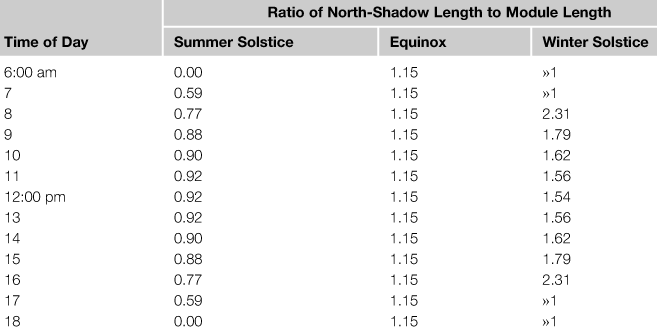
The above discussion applies to multiple rows of fixed, south-facing PV modules, where shadow length falling to the north dictates row spacing. We now consider rows of PV modules on single-axis trackers whose axes run north–south (a configuration seen in some large PV fields), and where shadow lengths to the west and east determine row spacing.
In this case the module tilt angle, β, varies throughout the day as the tracker follows the sun. Nominally the tilt angle would be set perpendicular to the sun’s altitude, i.e., β = π/2 − α (or equal to the zenith angle). However when the sun is low on the horizon, the modules would be tilted almost vertical, creating severe shading between rows of any spacing. To overcome this, computer-controlled trackers can be employed that decrease the module’s tilt in the early morning and late afternoon, a technique known as back-tracking. The increase in electricity yield from the avoided shading more than offsets the decrease in yield from greater incidence angle of sunlight on the modules during these times. Back-tracking allows module rows to be more closely spaced for the same yield, at the expense of a more sophisticated tracking control system.
9.6.4 Tilting versus spacing
Shading leads to a fundamental trade-off in the design of PV systems between tilting (fixed or tracking) and spacing (Denholm and Margolis, 2007). Tilting maximizes energy yield per unit area of module. However because tilting generally requires greater module spacing—both to reduce shading and to allow access for maintenance—it leads to a net decrease in energy yield per unit area of land, while also increasing mechanical complexity and capital cost of the system.
This effect is quantified in a simulation of tilting systems at Kansas City, which represents an energy density equal to the USA average value (Denholm and Margolis, 2007). The results are shown in Table 9.9, in which 3.5–5 m of spacing is assumed for the ground-mounted systems. It is seen that, in terms of yield per land area, the greater yield per module from tilting and tracking is outweighed by the greater spacing.
Table 9.9
Results of a Simulation for Tilting PV Modules in Kansas City, USA
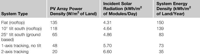
Denholm and Margolis (2007).
It follows that a key relationship that determines the attractiveness of tilting is that between the price of PV modules and the price of land (or roof space). Expensive modules and cheap land make it attractive to tilt those modules; expensive land and cheap modules encourages maximizing yield per land area through less tilt and closer spacing. The dramatic fall in PV module prices in recent years has thus decreased the relative attractiveness of tilting and tracking.
Leave a Reply