Details of this type of collector are given in Chapter 3, Section 3.2.1. As was seen in Chapter 3, parabolic trough collectors are the most mature solar technology to generate heat at temperatures up to 400 °C for solar thermal electricity generation or process heat applications. The biggest application of this type of system is the nine southern California power plants known as solar electric generating systems (SEGS), which have a total installed capacity of 354 MWe (Kearney and Price, 1992). Details on these plants are given in Table 10.2 (LUZ, 1990). As can be seen, SEGS I is 13.8 MWe, SEGS II–VII are 30 MWe each, and SEGS VIII and IX are 80 MWe each. These have been designed, installed, and operated in the Mojave Desert of southern California, the first one since 1985 and the last one since 1991. These plants are based on large parabolic trough concentrators providing steam to Rankine power plants. They generate peaking power, which is sold to the Southern California Edison utility. These plants were built in response to the 1970s oil crises, when the U.S. government gave tax and investment incentives on alternative energy, totaling to nearly 40% of their costs. Due to the research and development, economies of scale, and accumulated experience, there was a fall in cost of the parabolic trough generated electricity from US$0.30/kWh in 1985, when the first plant was built, to US$0.14/kWh in 1989, when the seventh plant of the cluster was built—a fall of more than 50% in four years. Today, California’s parabolic trough plants have generated well over 15,000 GWh of utility-scale electricity with 12,000 GWh from solar energy alone, which is more than half of all solar electricity ever generated (Taggart, 2008a). This represents about US$2 billion worth of electricity sold over the last 20 years. The nine plants continue to perform as well or even better than when first installed. These plants have accumulated more than 210 plant-years of operating experience.
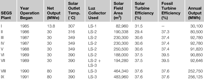
Table 10.2
Characteristics of SEGS Plants
Parabolic solar collectors focus sunlight onto a receiver pipe through which a synthetic oil circulates. The current synthetic oil is an aromatic hydrocarbon, biphenyl-diphenyl oxide, trademark Monsanto Therminol VP-1. The synthetic oil is then piped through a heat exchanger to produce steam that drives a conventional electricity-generating turbine. As with other renewable technologies, no pollutants are emitted in the process of generating electricity. A natural gas system hybridizes the plants and contributes 25% of their output. The plants can supply peaking power, using solely solar energy, solely natural gas, or a combination of the two, regardless of time or weather. Fossil fuel can be used to superheat solar-generated steam (SEGS I) in a separate fossil-fired boiler to generate steam when insufficient solar energy is available (SEGS II–VII), or in an oil heater in parallel with the solar field when insufficient solar energy is available (SEGS VIII–IX). The most critical time for power generation and delivery, and the time in which the selling price of the power per kWh is highest, is between noon and 6 pm in the summer months of June to September. The operating strategy is designed to maximize solar energy use. The turbine-generator efficiency is best at a full load; therefore, the natural gas supplement is also used to allow full load operation, which maximizes plant output. A photograph of a typical system is shown in Figure 10.2.
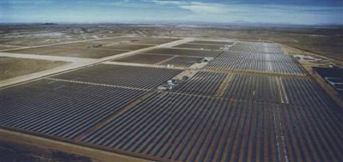
FIGURE 10.2 Photograph of a SEGS plant. http://www.sandia.gov/
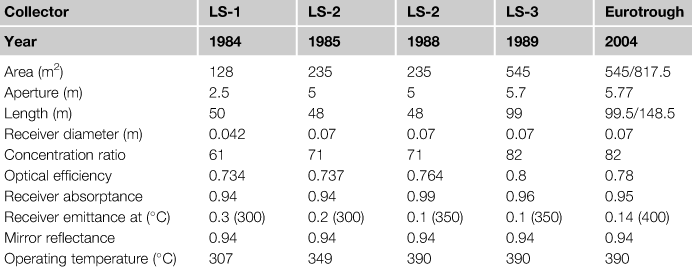
The basic component of the solar field is the solar collector assembly. Such an assembly is an independently tracking parabolic trough collector made of the metal support structure on which the parabolic reflectors (mirrors) are installed, together with the receiver tubes and supports. The tracking system includes the drive, sensors, and controller. Table 10.3 shows the design characteristics of the Luz collectors used in the California plants and Eurotrough, which is the product of a European research project. By combining the data shown in Table 10.3 with those of the nine plants shown in Table 10.2, it can be seen that the general trend was to build larger collectors with higher concentration ratios so as to maintain high collector efficiency at higher fluid outlet temperatures.
Table 10.3
Luz and Eurotrough Solar Collector Characteristics
The major components of the systems are the collectors, the fluid transfer pumps, the power generation system, the natural gas auxiliary subsystem, and the controls. The reflectors are made of black-silvered, low-iron float glass panels, which are shaped over parabolic forms. Metallic and lacquer protective coatings are applied to the back of the silvered surface. The glass is mounted on truss structures and the position of large arrays of modules is adjusted by hydraulic drive motors. The receivers are 70 mm in diameter steel tubes (except for LS-1) with cement selective surfaces surrounded by a vacuum glass jacket in order to minimize heat loss.
Maintenance of high reflectance is critical to plant operation. With a total of 2315 × 103 m2 of mirror area, mechanized equipment has been developed for cleaning the reflectors, which is done regularly, at intervals of about two weeks.
Tracking of the collectors is controlled by sun sensors that utilize an optical system to focus solar radiation on two light-sensitive diodes. Any imbalance between the two sensors causes the controller to give a signal to correct the positioning of the collectors; the resolution of the sensor is 0.5°. There is a sensor and controller on each collector row, which rotate about horizontal north–south axes, an arrangement that results in slightly less energy incident on them over the year but favors summertime operation when peak power is needed.
Parabolic trough technology proved to be tough, dependable, and proven. They are sophisticated optical instruments, and today, the second-generation parabolic troughs have more precise mirror curvature and alignment, which enables them to have higher efficiency than the first plants erected in California. Other improvements include the use of a small mirror on the backside of the receiver to capture and reflect any scattered sun rays back onto the receiver, direct steam generation into the receiver tube to simplify the energy conversion and reduce heat loss, and the use of more advanced materials for the reflectors and selective coatings of the receiver. Particularly, research and development, which aims to reduce the cost in half in the coming years, includes:
• Higher-reflectivity mirrors.
• More sophisticated sun-tracking systems.
• Better receiver selective coatings, with higher absorptance and lower emittance.
• Better mirror-cleaning techniques.
• Better heat-transfer techniques by adopting direct steam generation.
• Optimized hybrid integrated solar combined-cycle system (ISCCS) designs to allow maximum solar input.
• Development of trough system designs that provide the best combination of low initial cost and low maintenance.
• Development of thermal storage options that allow nighttime dispatch of solar-only trough plants.
In the previous section, the possibility of using heat storage is mentioned. Parabolic trough collector systems produce heat at about 400 °C. This heat can be stored in an insulated container and used during nighttime. Currently molten salt is used for this purpose, and this system was used in the California plants, the newly built plants, and the plants that are under construction or planned for the near future. Since research in this field is ongoing, this could change in the coming years.
10.2.1 Description of the PTC power plants
Parabolic trough solar collector technology is currently the most proven solar thermal collector technology. This is primarily due to the nine plants operating in California’s Mojave Desert since the mid-1980s. In these plants, large fields of parabolic trough collectors supply the thermal energy used to produce steam supplied to a Rankine steam turbine-generator cycle to produce electricity. Each collector has a linear parabolic reflector, which focuses the sun’s direct (or beam) radiation on a linear receiver located at the focus of the parabola. Figure 10.3 shows a process flow diagram, representative of the majority of plants operating today in California. The collector field consists of many large single-axis-tracking PTC collectors, installed in parallel rows aligned on a north–south horizontal axis and tracking the sun from east to west during the day to ensure that the sun is continuously focused on the linear receiver. A heat transfer fluid is circulated through the receiver, where it is heated by solar energy and returns to a series of heat exchangers in the power block to generate high-pressure superheated steam and back to the solar field. This steam is used in a conventional reheat steam turbine-generator to produce electricity. As shown in Figure 10.3, the steam from the turbine is piped to a standard condenser and returns to the heat exchangers with pumps so as to be transformed again into steam. The type of condenser depends on whether a large source of water is available near the power station. Because all plants in California are installed in a desert, cooling is provided with a mechanical draft wet cooling towers.
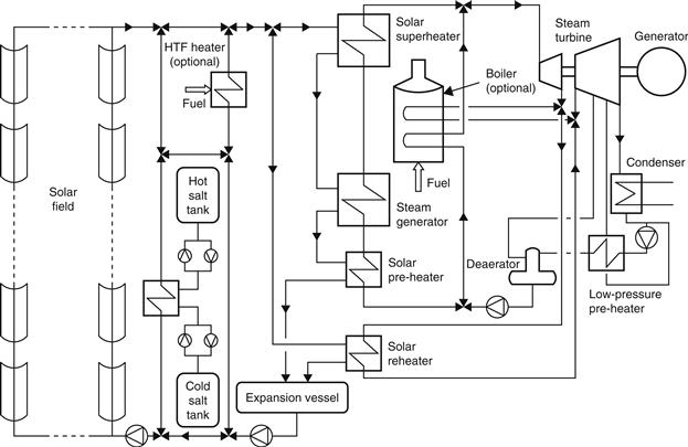
FIGURE 10.3 Schematic diagram of a solar Rankine parabolic trough system.
Parabolic trough plants are designed to use primarily solar energy to operate; if it is sufficient, this solar energy alone can operate the plants at the full rated power. During summer months, the plants operate at full rated electric output for 10–12 h/day. Because the technology can be easily hybridized with fossil fuels, the plants can be designed to provide firm peaking to intermediate load power. All plants in California, however, are hybridized to use natural gas as backup to produce electricity that supplements the solar output during periods of low solar radiation and nighttime. As shown in Figure 10.3, the natural gas-fired heater is situated in parallel to the solar field, or the optional gas-fired boiler steam reheater is located in parallel with the solar heat exchangers, to allow operation with either or both of the energy resources.
A synthetic heat transfer fluid is heated in the collectors and piped to the solar steam generator and superheater, where it generates the steam to supply the turbine. Reliable high-temperature circulating pumps are critical to the success of the plants, and substantial engineering effort has gone into assuring that pumps will stand the high fluid temperatures and temperature cycling. The normal temperature of the fluid returned to the collector field is 304 °C and that leaving the field is 390 °C.
As shown in Figure 10.3, the power generation system consists of a conventional Rankine cycle reheat steam turbine with feed-water heaters, deaerators, and other standard equipment. The condenser cooling water is cooled in forced draft cooling towers.
The evaporator generates saturated steam and demands feed-water flow from the feed-water pump. In a steam generator, the heat transfer oil is used to produce slightly superheated steam at 5–10 MPa (50–100 bar) pressure, which then feeds a steam turbine connected to a generator to produce electricity.
Usually, the SEGS plants incorporate a turbine that has both high- and low-pressure stages, with reheat of the steam occurring between the stages. The turbine operational limitations are, at minimum, 16.2 bar steam pressure and 22.2 °C superheat. When these conditions are not met, steam is diverted around the turbine to the condenser via a bypass circuit and fractional splitter. During start-up or shutdown, the fraction sent to the turbine varies linearly between 0 and 1. A throttling valve in the bypass loop provides the equivalent pressure drop as the turbine would provide under the same conditions.
The feed-water heaters are heat exchangers that condense steam extracted from the turbine to heat feed-water, thereby increasing the Rankine cycle efficiency.
The deaerator is a type of feed-water heater, where steam is mixed with sub-cooled condensate to produce saturated water at the outlet. This helps purge oxygen from the feed-water, controlling corrosion.
Steam exiting the turbine is condensed so that it can be pumped through the steam generation system.
A new design concept, which integrates a parabolic trough plant with a gas turbine combined-cycle plant, called the integrated solar combined-cycle system (ISCCS), is shown schematically in Figure 10.4. Such a system offers a possibility to reduce cost and improve the overall solar-to-electricity efficiency. As shown, the ISCCS uses solar heat to supplement the waste heat from a gas turbine to augment power in the steam Rankine bottoming cycle. In this system, solar energy is used to generate additional steam, and the gas turbine waste heat is used for preheating and steam superheating.
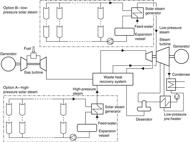
FIGURE 10.4 Schematic diagram of the integrated solar combined-cycle plant.
One of the most serious problems when working in a desert environment is cleaning dust from the parabolic mirrors. As a general rule, the reflectivity of glass mirrors can be returned to design levels with good washing. After considerable experience gained over the years, operating and maintenance procedures nowadays includes deluge washing and direct and pulsating high-pressure sprays, which use demineralized water for good effectiveness. Such operations are carried out during nighttime. Another measure that’s applied is periodic monitoring of mirror reflectivity, which can be a valuable quality control tool to optimize mirror-washing frequency and the labor costs associated with this operation.
The benefits of direct steam generation were outlined previously. This method was recently demonstrated in Plataforma Solar de Almeria, Spain, in a 500 m long test loop providing superheated steam at 400 °C and 10 MPa (100 bar). To keep a two-phase steam-water flow in a large number of long, parallel, and horizontal absorber tubes is a major technical challenge. The system must be able to maintain a constant turbine inlet conditions and avoid flow instabilities, even during spatially and temporally changing insolation. Control strategies have been developed based on extensive experimentation and modeling of two-phase flow phenomena.
10.2.2 Outlook for the technology
The experience of the California plants has shown some benefits and some negative impacts that should be considered in designing new plants. The benefits include:
• The provision of the lowest-cost solar-generated electricity for many years of operation;
• Daytime peaking power coverage and with hybridization the ability to provide firm power, even during cloudy periods and night;
• Enhanced environmental protection, because no emissions occur during solar operation; and
• Positive impacts on local economy because systems are labor intensive during both construction and operation.
• Heat transfer fluids could spill and leak, which can create problems in the soil;
• Water availability can be a significant issue in the arid regions that are best suited for trough plants. The majority of this water is required for the cooling towers;
• Parabolic trough plants require a considerable amount of land that cannot be used concurrently for other purposes; and
• Emissions occur when plants are operated with conventional fuels during hybrid operation.
Generally, in economic terms, by increasing the parabolic trough plant size, the cost of solar electricity is reduced. Cost reductions typically occur because of increased manufacturing volume, which lowers the cost per square meter, the relative initial cost to build a bigger plant, and operating and maintenance cost on a per-kilowatt-hour basis. Additionally, hybridization offers a number of potential benefits to solar plants, including reduced risk to investors and improved solar-to-electric conversion efficiency. Since fossil fuels are currently cheap, hybridization also provides a good opportunity to reduce the average cost of electricity from the plant.
The last issue to consider is thermal storage. The availability of low-cost thermal storage is important for the long-term cost reduction of solar trough technology and could significantly increase the potential market opportunities. For example, a plant located in California without fossil-fuel backup and thermal storage would produce electricity at an annual load factor of only 25%. The addition of thermal storage could increase this factor to about 50% because the plant would be able to work at non-solar times of the day and by allowing the solar field to be oversized. It should be noted, however, that attempting to increase the factor much above 50% would result in significant dumping of solar energy during summer months.
In 2007, the Nevada Solar One started operating in the state of Nevada. The Nevada Solar One plant uses the parabolic trough technology, and provides energy to Las Vegas. Nevada Solar One is a PTC system located near Boulder City, Nevada. It is a collaboration of Nevada Power Company and Sierra Pacific Resources and the construction completed in June 2007. It occupies 400 acres and the total capacity is 64 MW, harnessing solar energy to power more than 14,000 homes every year. It represents a major renewable-energy success story and has the potential to compete directly with conventional fossil fuel-powered technologies. Nevada Solar One is an environmentally friendly, renewable utility-scale power solution that creates power with near-zero carbon emissions. It is estimated that the CO2 emissions avoided are the equivalent to taking approximately 20,000 cars off the road annually.
It is estimated that an energy project utilizing concentrating solar power technology deployed over an area of approximately 100 × 100 miles in the Southwest U.S. could produce enough power for the entire U.S. annually.
A significant parabolic trough plant that is under construction is the 280 MW Solana Generating Station installed at Gila Bend, near Phoenix, Arizona, scheduled to finish in 2013. The Solana Generating Station (solana means a sunny place in Spanish) requires 7.7 km2 PTCs to be installed and will produce enough electricity to satisfy about 70,000 homes. This would be the largest parabolic trough plant in the United States and is expected to be 20–25% more efficient than the California plants, mainly due to a reduction in heat loss from the receiver. Recently Andasol 1 and 2, the first parabolic trough power plants in Europe, were put in operation near Guadix in Andalusia, Spain (2009). Their name is a combination of Andalusia and Sol (Sun in Spanish). The plants are located at high altitude (1100 m) in a semi-arid climate, so the site receives exceptionally high annual direct insolation of about 2200 kWh/m2 per year. Each plant has a gross electricity output of 50 MWe, producing around 180 GWh per year. Each collector has a surface of 51 ha (hectares) and needs about 200 ha of land. The Andasol power plants are used to meet the Spanish power demand caused primarily by air-conditioning units. This peaks in the early afternoon at the time when both solar radiation and the plants’ power output are also at their peak.
The Andasol plants have a thermal storage system that absorbs part of the heat produced in the solar collector field during the day. This heat is stored in a molten salt mixture (60% sodium nitrate and 40% potassium nitrate). The power system produces electricity using this heat during the evening, or cloudy weather. The thermal reservoir holds 1010 MWh of heat, enough to run the steam turbine for about 7.5 h at full-load. The thermal reservoirs consist of two tanks, 14 m in height and 36 m in diameter, containing molten salt. Andasol 1 and 2 are able to supply environmentally friendly solar electricity for up to 400,000 people. Andasol 3, which is of the same capacity as Andasol 1 and 2, is almost near completion. Other plants are planned for Spain, Egypt, Algeria, and Morocco.
As indicated previously, the best location of CSP plants is in isolated desert regions. Very few people live in these places, however, so the transmission of electricity to cities could be problematic and costly. Therefore, a long-term development of the technology depends on the willingness of governments or utility companies to erect high-capacity power lines to transfer the CSP electricity produced in remote regions to cities. A possibility to alleviate this problem is to use solar energy to produce hydrogen as an energy carrier, which can be transported more easily. Hydrogen can then be used in a fuel cell to produce electricity (see Chapter 7). Another attractive possibility to increase the penetration of CSP in the energy supply system is to combine it with other systems requiring thermal or electrical energy to operate. A good example is desalination, using either electricity with a reverse osmosis system or thermal energy with multiple-effect or multi-stage evaporators (see Chapter 8). Such a synergy could create large-scale environmentally friendly electricity and water solutions for many sunny places of the world.
Leave a Reply