
Thermal solar power plants are similar to the conventional ones with the exception that a field of concentrating solar collectors replaces the conventional steam boiler. In hybrid plants, a conventional boiler is also present, operating on conventional fuel, usually natural gas, whenever there is a need. Therefore, the thermal analysis of solar power plants is similar to that of any other plant and the same thermodynamic relations are applied. The analysis is greatly facilitated by drafting the cycle on a T–s diagram. In these cases, the inefficiencies of pump and steam turbine should be considered. In this section, the equations of the basic Rankine power cycle are given and two of the more practical cycles, the reheat and the regenerative Rankine cycles, are analyzed through two examples. To solve the problems of these cycles, steam tables are required. Alternatively, the curve fits shown in Appendix 5 can be used. The problems that follow were solved by using steam tables.
The basic Rankine cycle is shown in Figure 10.11(a) and its T–s diagram in Figure 10.11(b).
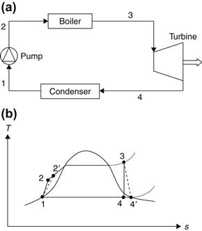
FIGURE 10.11 Basic Rankine power plant cycle. (a) Basic Rankine cycle schematic. (b) T–s diagram.
As can be seen in Figure 10.11, the actual pumping process is 1–2′ and the actual turbine expansion process is 3–4′. The various parameters are as follows:
Turbine efficiency,
![]() (10.1)
(10.1)
Pump efficiency,
Net work output,
![]() (10.3)
(10.3)
Heat input,
![]() (10.4)
(10.4)
Pump work,
![]() (10.5)
(10.5)
Cycle efficiency,
![]() (10.6)
(10.6)
h = specific enthalpy (kJ/kg);
v = specific volume (m3/kg); and
P = pressure (bar) = 105 N/m2.
Generally, the efficiency of a Rankine cycle can be improved by increasing the pressure in the boiler. To avoid the increase of moisture in the steam coming out from the turbine, steam is expanded to an intermediate pressure and reheated in the boiler. In a reheat cycle, the expansion takes place in two turbines. The steam expands in the high-pressure turbine to some intermediate pressure, then passes back to the boiler, where it is reheated at constant pressure to a temperature that is usually equal to the original superheat temperature. This reheated steam is directed to the low-pressure turbine, where is expanded until the condenser pressure is reached. This process is shown in Figure 10.12.
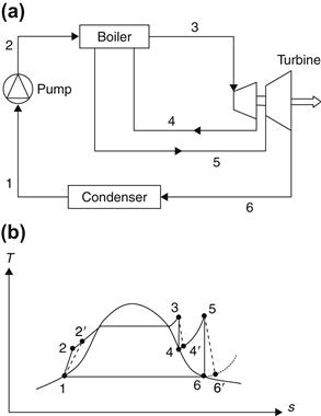
FIGURE 10.12 Reheat Rankine power plant cycle. (a) Reheat Rankine cycle schematic. (b) T–s diagram.
The reheat cycle efficiency is given by:
EXAMPLE 10.1
The steam in a reheat Rankine cycle leaves the boiler and enters the turbine at 60 bar and 390 °C. It leaves the condenser as a saturated liquid. The steam is expanded in the high-pressure turbine to a pressure of 13 bar and reheated in the boiler at 390 °C. It then enters the low-pressure turbine, where it expends to a pressure of 0.16 bar. Estimate the efficiency of the cycle if the pump and turbine efficiency is 0.8.
Solution
At point 3, P3 = 60 bar and T3 = 390 °C. From superheated steam tables, h3 = 3151 kJ/kg and s3 = 6.500 kJ/kg K.
At point 4, s4 = s3 = 6.500 kJ/kg K. From the problem definition, P4 = 13 bar. From steam tables, h4 = 2787 kJ/kg. To find h4′, we need to use Eq. (10.1) for turbine efficiency:
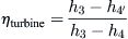
or h4′ = h3 − ηturbine(h3 − h4) = 3151 − 0.8(3151 − 2787) = 2860 kJ/kg.
At point 5, P5 = 13 bar and T5 = 390 °C. From superheated steam tables, h5 = 3238 kJ/kg and s5 = 7.212 kJ/kg K.
At point 6, s6 = s5 = 7.212 kJ/kg K. From the problem definition, P6 = 0.16 bar. From steam tables, s6f = 0.772 kJ/kg K and s6g = 7.985 kJ/kg K. Therefore, at this point, we have a wet vapor and its dryness fraction is:
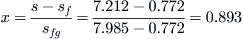
At a pressure of 0.16 bar, hf = 232 kJ/kg and hfg = 2369 kJ/kg; therefore, h6 = hf + xhfg = 232 + 0.893 × 2369 = 2348 kJ/kg.
To find h6′, we need to use Eq. (10.1) for turbine efficiency:

At point 1, the pressure is also 0.16 bar. Therefore, from steam tables at saturated liquid state, we have v1 = 0.001015 m3/kg and h1 = 232 kJ/kg.
From Eq. (10.5),

Therefore, h2′ = 232 + 7.592 = 239.6 kJ/kg.
Finally, the cycle efficiency is given by Eq. (10.7):

The efficiency of the simple Rankine cycle is much less than the Carnot efficiency, because some of the heat supplied is transferred while the temperature of the working fluid varies from T3 to T1. If some means could be found to transfer this heat reversibly from the working fluid in another part of the cycle, then all the heat supplied from an external source would be transferred at the upper temperature and efficiencies close to the Carnot cycle efficiency could be achieved. The cycle where this technique is used is called a regenerative cycle.
In a regenerative cycle, expended steam is extracted at various points in the turbine and mixed with the condensed water to preheat it in the feed-water heaters. This process, with just one bleed point, is shown in Figure 10.13, in which the total steam flow rate is expanded to an intermediate point 6, where a fraction, f, is bled off and taken to a feed-water heater; the remaining (1 − f) is expanded to the condenser pressure and leaves the turbine at point 7. After condensation to state 1, the (1 − f) kg of water is compressed in the first feed pump to the bleeding pressure, P6. It is then mixed in the feed-water heater with f kg of bled steam in state 6 and the total flow rate of the mixture leaves the heater in state 3 and is pumped to the boiler, 4.
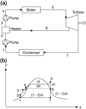
FIGURE 10.13 Rankine power plant cycle with regeneration. (a) Regenerative Rankine cycle schematic. (b) T–s diagram.
Although one feed-water heater is shown in Figure 10.13, in practice, a number of them can be used; the exact number depends on the steam conditions. Because this is associated with additional cost, however, the number of heaters and the proper choice of bleed pressures is a matter of lengthy optimization calculations. It should be noted that if x number of heaters are used, x + 1 number of feed pumps are required.
The regenerative cycle efficiency is given by:
![]() (10.8)
(10.8)
where f = fraction of steam in the turbine bled at state 6 to mix with the feed-water.
In this cycle, the enthalpy at state 3 can be found by an energy balance as:
![]() (10.9)
(10.9)
from which:
![]() (10.10)
(10.10)
EXAMPLE 10.2
In a regenerative cycle, steam leaves the boiler to enter a turbine at a pressure of 60 bar and a temperature of 500 °C. In the turbine, it expands to 5 bar, then a part of this steam is extracted to preheat the feed-water in a heater that produces saturated liquid, also at 5 bar. The rest of the steam is further expanded in the turbine to a pressure of 0.2 bar. Assuming a pump and turbine efficiency of 100%, determine the fraction of steam used in the feed-water heater and the cycle efficiency.
Solution
At point 5, P5 = 60 bar and T5 = 500 °C. From superheated steam tables, s5 = 6.879 kJ/kg K and h5 = 3421 kJ/kg.
At point 6, s6 = s5 = 6.879 kJ/kg K and P6 = 5 bar. Again from superheated steam tables by interpolation, h6 = 2775 kJ/kg.
At point 7, P7 = 0.2 bar and s7 is also equal to s5 = 6.879 kJ/kg K. At this pressure, sf = 0.832 kJ/kg K and sg = 7.907 kJ/kg K. Therefore, the dryness fraction is:
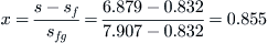
At the same pressure, hf = 251 kJ/kg and hfg = 2358 kJ/kg. Therefore, h7 = hf + xhfg = 251 + 0.855 × 2358 = 2267 kJ/kg.
At point 1, the pressure is 0.2 bar, and because we have saturated liquid, h1 = hf = 251 kJ/kg and v1 = 0.001017 m3/kg.
At point 2, P2 = 5 bar and as h2 − h1 = v1(P2 − P1), h2 = 251 + 0.001017(5 − 0.2) × 102 = 251.5 kJ/kg.
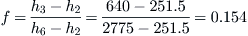
At point 3, P3 = 5 bar. From the problem definition, the water at this point is a saturated liquid. So, v3 = 0.001093 m3/kg and h3 = 640 kJ/kg. Using Eq. (10.9), h3 = fh6 + (1 − f)h2, or:
At point 4, P4 = 60 bar. Therefore, h4 − h3 = v3(P4 − P3) or h4 = h3 + v3(P4 − P3) = 640 + 0.001093(60 − 5) × 102 = 646 kJ/kg.
Finally, the cycle efficiency is obtained from Eq. (10.8):

Leave a Reply