The solar updraft tower is a renewable-energy power plant for generating electricity from solar power. The principle of operation of a solar chimney or updraft power plant is that because of its lower density hot air rises and creates a draft. The system consists of a chimney, a solar energy collector and wind turbines. In the collector, which is a large area of covered land, air is heated by solar radiation under a transparent (glass) or translucent (plastic) roof. This heat is forced upward through the chimney thereby creating a wind force as the joint between the roof and the tower base is airtight. Suction from the tower then draws in more hot air from the collector, and cold air comes in from the outer perimeter.
By placing wind turbines at the base of the tower the wind force can be used to produce electricity. One advantage of the system is that the collector itself functions as a greenhouse and could be used for growing various crops. The solar updraft power technology has relatively low conversion efficiency and relatively high investment costs per MWh of electricity produced, but the operating costs are very low. The technology is particularly suitable in remote areas where low-value land can be used for the heat collection.
A schematic diagram of a solar updraft tower is shown in Figure 10.14. Solar updraft towers make use of differences in temperatures of air near the ground and at the top of the tower or chimney. Through the chimney effect, i.e., forcing the air through a relatively small opening, the wind force becomes very strong. By placing a vertical wind turbine at the base of the tower or a number of horizontal turbines in a ring around the base of the tower, this updraft force can be used to produce electricity. As the only source of energy is solar energy, the solar updraft tower functions as a solar thermal power plant. Over the day the ground gets heated and over the night it gives its warmth to the ascending collector air. Continuous 24 h operation can be best achieved by placing water-filled tubes or bags under the roof. The water heats up during daytime and releases its heat at night. The tubes are filled with water only once (no further refilling is required) to increase the effect. Black colored bodies have the ability to absorb short wavelength radiation during the day to heat the water and emit long wavelength heat at night to warm the air.
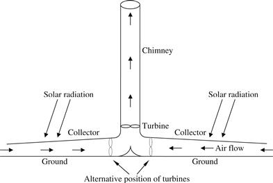
FIGURE 10.14 Schematic diagram of a solar updraft tower.
Hot air for the solar tower is produced by the greenhouse effect in a simple air collector consisting of a nearly horizontal glass or plastic glazing installed several meters above the ground. The height of the glazing increases near the tower base, which has a smooth entrance so that the air is diverted to vertical movement with minimum friction loss. Therefore, the ground under the transparent roof is heated and transfers its heat to the air flowing radially inside the tower.
The requirement of a relatively large area implies that the technology is particularly suitable in those countries which have large areas of desert-type land.
A good review on the developments and advancement of solar chimney power plants is presented by Bernandes (2010).
The energy efficiency of the solar updraft tower is low. Therefore, a relatively large area is required for collecting the heated air in combination with a tall chimney. It is estimated that for a 200 MW capacity plant, the solar collector should have an area of 38 km2 and the chimney height is 1000 m (Schlaich et al., 2005). The conversion efficiency of such a plant would be about 0.5% (or 1 kWh/m2). The capital costs for such a plant would be relatively high as it requires a specialized expertise mainly for the tower construction, but the running costs would be very low and concern mainly maintenance of the wind turbines. However, when plastic is chosen as the cover for the solar collector, then this will require replacement every few years. Producing electricity with such a 200 MW solar tower would cost €0.07 per kWh whereas it would cost €0.21 per kWh for a smaller 5 MW plant due to economies of scale (Schlaich et al., 2005).
10.6.1 Initial steps and first demonstration
A Spanish artillery colonel Isidoro Cabanyes in 1903 provided one of the earliest descriptions of a solar chimney power station. He proposed a solar engine project in which an air heater was attached to a house with a chimney. In the house a kind of wind propeller was placed to produce electricity (Bernandes, 2010).
In 1926 Bernard Dubos proposed to the French Academy of Sciences the construction of a Solar Aero-Electric Power Plant in North Africa with its solar chimney on the slope of the high mountain. The author claimed that an air speed of 50 m/s can be reached in the chimney, and that this enormous amount of energy can be extracted by wind turbines (Bernandes, 2010).
Following these original concepts, the first prototype of a solar updraft tower was erected in 1982 in Manzanares, 150 km south of Madrid, Spain (see Figure 10.15). The chimney height was 195 m and its diameter was 5.08 m. The collector area was 46,000 m2 (about 11 acres, or 244 m diameter). This prototype is considered as a small-scale experimental model and although it was not intended for power generation, the peak power output was about 50 kW. During the testing phase (1982–1989) different glazing materials were tested. Additionally, parts of the collector area were used as an actual greenhouse, growing plants under the glass. The prototype was built with financial support from the Federal Republic of Germany, (Haaf et al., 1983). Preliminary test results including energy balances, collector efficiency values, pressure losses due to friction and losses in the turbine section were presented by Haaf (1984). Unfortunately the tower’s guy-wires were not protected against corrosion and failed due to rust and storm winds. The tower blew over and was decommissioned in 1989.
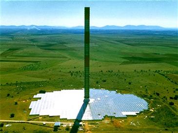
FIGURE 10.15 Photograph of the Manzanares solar updraft tower plant in Spain.
The aim of this research project was to verify, through field measurements, the performance estimated from calculations based on theory, and to examine the influence of individual components on the plant’s output and efficiency under realistic engineering and meteorological conditions. The main dimensions and technical data for the experimental plant are shown in Table 10.4.
Table 10.4
Main Dimensions and Technical Specifications of the Manzanares Prototype
| Item | Value |
| Nominal output | 50 kW |
| Tower height | 194.6 m |
| Tower radius | 5.08 m |
| Mean collector radius | 122.0 m |
| Mean roof height | 1.85 m |
| Number of turbine blades | 4 |
| Operation modes | Stand-alone or grid connected |
| Typical collector air temperature increase | 20 K |
| Collector covered with plastic membrane | 40,000 m2 |
| Collector covered with glass | 6000 m2 |
Completion of the construction phase in 1982 was followed by an experimental phase, the purpose of which was to demonstrate the operating principle of a solar tower. The goals of this phase of the project were to (Schlaich et al., 2005):
1. Obtain data on the efficiency of the technology developed;
2. Demonstrate fully automatic, power plant-like operation with a high degree of reliability; and
3. Record and analyze operational behavior and physical relationships on the basis of long-term measurements.
The tower tube stood on a supporting ring 10 m above ground level. A pre-stressed membrane of plastic-coated fabric, shaped to provide good flow characteristics, formed the transition between the roof and the tower. The tower was guyed at four levels, and in three directions, to foundations secured with rock anchors. The turbine was supported independently of the tower on a steel framework 9 m above the ground level. The four blades of the turbine were adjustable according to the face velocity of the air in order to achieve an optimal pressure drop across the turbine blades. Maximum vertical wind velocity during turbine operation was 12 m/s. The collector roof of the solar tower not only has to have a transparent or translucent covering, it must also be durable and of low cost. A variety of plastic sheets and glass was considered in order to determine which was the best. Glass can resist heavy storms for many years without harm and prove to be self-cleaning due to the occasional rains. The plastic membranes were clamped to a frame and stressed down to the ground at the center by use of a plate with drain holes. The initial investment cost of plastic membranes is lower than that of glass; however, in the Manzanares pilot plant the membranes got brittle with time due to the UV radiation and thus tended to tear. Materials with temperature and UV stability and design improvements achieved in recent years may overcome this disadvantage.
In developing countries, the technology was tested in Botswana in 2005 where a small 22 m tall chimney was built with a collector area of 160 m2. The chimney was made of polyester material and the roof of the collector area was made of glass.
The solar updraft tower plant has notable advantages in comparison with other power production technologies (Schlaich, 1995):
• The collector uses both direct and diffuse radiation.
• The ground provides a natural heat storage, which allows 24 h operation. This can be enhanced with additional water tubes or bags placed under the collector roof to absorb part of the radiated energy during the day and release it into the collector at night.
• The low number of rotating parts ensures good reliability.
• No cooling water is necessary for its operation in arid areas.
• Simple materials and known technologies are used for its construction.
• Developed countries are able to implement such technology without costly technological efforts and without high foreign currency expenditure using local resources and work force.
Additionally, these plants can have a much longer life time than conventional power plants, they have minimum operation and maintenance requirements, they are environmentally friendly as there are no CO2 emissions during operation and they provide sustainable and affordable source of electricity.
Solar updraft towers also have features that make them less suitable for some sites (Schlaich et al., 2005):
• They require large areas of flat land, which should be available at low cost with no competing usage, like for example for intensive agriculture.
• They are not safe in earthquake prone areas, as in this case tower costs would increase drastically.
• Zones with frequent sand storms should also be avoided, as either collector performance losses or collector operation and maintenance costs would be substantial.
10.6.2 Thermal analysis of solar updraft tower plants
The fundamental analysis of solar updraft tower plants that influence the power output of a solar tower is presented by Schlaich et al. (2005). Generally, the power output P of the solar tower can be calculated as the solar input ![]() multiplied by the efficiencies of collector (ηc), tower (ηtr) and turbine/s (ηt), given by:
multiplied by the efficiencies of collector (ηc), tower (ηtr) and turbine/s (ηt), given by:
![]() (10.11)
(10.11)
where ηp is the total efficiency of the plant comprising the collector, tower, and turbine. The solar energy input ![]() into the system can be written as the product of global horizontal radiation G and collector area Ac:
into the system can be written as the product of global horizontal radiation G and collector area Ac:
![]() (10.12)
(10.12)
Due to the chimney effect, the tower essentially converts the heat flow produced by the collector into kinetic and potential energies. Therefore the driving force is due to the density difference of the air caused by the temperature rise in the collector. The pressure difference Δptot produced between the tower base (or collector outlet) and the ambient air is given by:
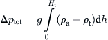 (10.13)
Therefore, Δptot increases with tower height. Neglecting friction losses, the pressure difference Δptot can be subdivided into a static and a dynamic component:
![]() (10.14)
(10.14)
The static pressure difference drops at the turbine, whereas the dynamic component represents the kinetic energy of the airflow. With the total pressure difference and the volume flow of the air at Δps = 0 the total power (Ptot) that the air flow carries is given by:
![]() (10.15)
(10.15)
With the help of Eq. (10.15) the efficiency of the tower can be obtained, given by:
![]() (10.16)
(10.16)
It should be noted that the actual separation of the pressure difference into static and dynamic components depends on the energy taken up by the turbine. Without a turbine, the maximum flow speed of Vt,max is obtained and the whole pressure difference is used to accelerate the air and thus all energy is converted into kinetic energy:
Using the Boussinesq approximation, the speed reached by free convection currents can be obtained from:
![]() (10.18)
(10.18)
where ΔT is the temperature rise between ambient and collector outlet [=tower inlet].
Finally, by replacing Eq. (10.18) into Eq. (10.17) and then into Eq. (10.16), and considering that ![]() the tower efficiency is given by:
the tower efficiency is given by:
![]() (10.19)
(10.19)
where, g is the acceleration due to gravity (m2/s), Ht is the tower height (m), cp is the air heat capacity (J/kg K) and To is the ambient temperature (K). For instance, with a chimney height of 1000 m and standard conditions for temperature and pressure, the tower efficiency achieves a maximum value of 3%. Considering a collector efficiency (ηc) of 60% and a turbine efficiency (ηtr) of 80%, the total efficiency of the plant (ηp) reaches 1.4%, as ηp = ηc ηtr ηt = 0.6 × 0.8 × 0.03 = 0.014.
The simplified analysis presented above indicates that the tower efficiency actually depends only on its height, which is the basic characteristic of the solar updraft tower. Additionally, for heights of 1000 m, the deviation from the exact solution, caused by the Boussinesq approximation (Eq. 10.18), is negligible (Schlaich et al., 2005). By using Eqs. (10.11), (10.12) and (10.19) it can be found that solar tower power output is proportional to the collector area and tower height. Additionally, as the electrical output of the solar tower is proportional to the volume included within the tower height and collector area, the same output may result from a large tower with a small collector area and vice versa (Schlaich et al., 2005). Although this simplified analysis is not strictly valid when friction losses in the collector are considered, it is a good rule of thumb as long as the solar collector diameter is not too large (Schlaich et al., 2005).
The tower (or chimney) is the plant’s actual thermal engine. It is a pressure tube with low friction loss. The updraft velocity of the air is approximately proportional to the air temperature rise (ΔT) in the collector and to the tower height as indicated by Eq. (10.18). In a large multi-megawatt solar updraft tower, the collector could rise the air temperature by about 30–35 K, which could produce a relatively small updraft velocity in the tower of about 15 m/s at nominal electric output.
Concerning the technology, towers of 1000 m height are a challenge, but they can be built today as complicated skyscrapers are now built even in earthquake countries like Japan. The solar updraft tower is much simpler, as a large diameter hollow cylinder which has much fewer demands in comparison with inhabited buildings, is required. The respective structural approaches are well known and have been used for many years in cooling towers. Recent detailed static and structural research showed that it is appropriate to stiffen the tower at several heights with cables arranged like spoke wheels within the tower and this allows thinner walls to be used (Schlaich et al., 2005).
Leave a Reply