
Plane Walls with Convection on Sides
There are many cases in practice when different materials are constructed in layers to form a composite wall. This wall may be composed of plaster layer, brick layer, tiles layer, etc. as shown in Figure 7.3.
In Figure 7.3 there are three layers A, B, C, of thickness LA, LB, and LC, respectively. The thermal conductivities of the layers are kA, kB, and kC. On one side of the composite wall there is a fluid at temperature t∞1 and heat transfer coefficient from fluid to wall is h1; on other side of the composite wall there is fluid at temperature t∞2 and the heat transfer coefficient from fluid to wall is h2. Let the temperature of the wall in contact with fluid on one side is t1 and on other side t4. The interface temperatures of the composite wall are t2 and t3. To solve the heat flow problem an analogous of electrical current may be used. The heat flow is caused by temperature difference whereas the current flow is caused by a potential difference. Hence, it is possible to postulate a thermal resistance analogous to an electrical resistance. From Ohm’s law we have, V=IR or I=V/R, where V is potential difference, I is current and R is resistance.
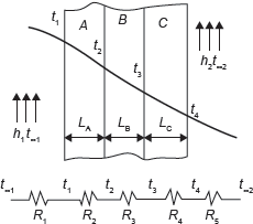
Figure 7.3 Plane Walls with Convection on Sides
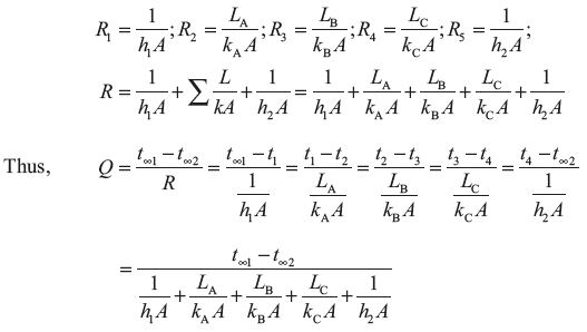
Thermal resistance, ![]() and thermal resistance for a fluid film,
and thermal resistance for a fluid film, ![]() where Q is analogous to I and Δt is analogous to ΔV.
where Q is analogous to I and Δt is analogous to ΔV.
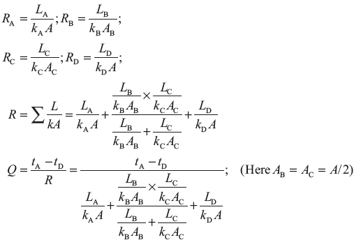
Example 7.2: Derive the expression for the heat transfer through series and parallel composite walls as shown in Figure 7.4.
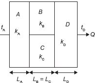
Figure 7.4 Heat Transfer Through Composite Wall
Solution:
The electrical current analogy of the heat transfer is shown in Figure 7.5.
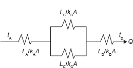
Figure 7.5 Electrical Analogy of Heat Transfer for Composite Wall is Shown in Figure 7.4
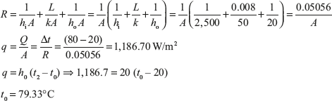
Example 7.3: A steel tank of wall thickness 8 mm contains water at 80°C. Calculate the rate of heat loss per m2 of tank surface area when the atmospheric temperature is 20°C. The thermal conductivity of mild steel is 50 W/m K, and the heat transfer coefficients for the inside and outside of the tank are 2,500 and 20 W/m2K, respectively. Calculate also the temperature of the outside surface of the tank.
Solution:
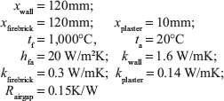
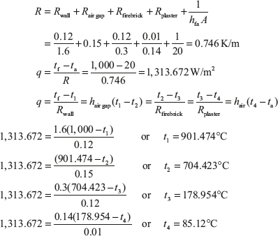
Example 7.4: A furnace wall consists of 120 mm thick refractory brick and 120 mm thick insulating firebrick separated by an air gap as shown in Figure 7.6. The outside wall is covered with a 10 mm thickness of plaster. The inner surface of the wall is at 1,000°C and the room temperature is 20°C. Calculate the rate at which heat is lost per m2 of wall surface. The heat transfer coefficient from the outside wall surface to the air on the room is 20 W/m2K, and the resistance to heat flow of the air gap is 0.15 K/W. The thermal conductivity of refractory brick, insulating firebrick and plaster are 1.6, 0.3 and 0.14 W/m K, respectively. Calculate also each interface temperature of the outside of the wall.
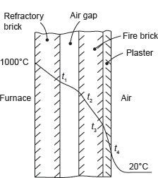
Figure 7.6 Composite Walls
Given:
Heat Transfer Through Hollow Cylinder
Consider a cylinder of internal radius r1 and external radius r2 as shown in Figure 7.7. Let the inside and outside temperatures be t1 and t2, respectively. Consider the heat flow through a small element of thickness dr at any radius r, where the temperature is t. Let the thermal conductivity of the material be k, temperature of fluid flow inside the cylinder be tf1, heat transfer coefficient be hf1, temperature of fluid flow outside the cylinder be tf2 and heat transfer coefficient be hf2. The heat transfer through the elemental area of length l can be given by,
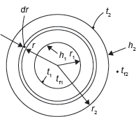
Figure 7.7 Heat Transfer Through Cylindrical Wall
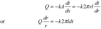
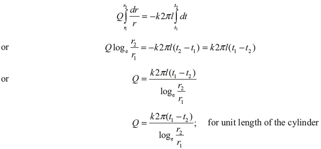
Integrating between the inside and outside surfaces,
If we put mean area Am and mean radius rm in the above equation as
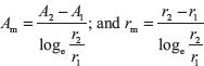
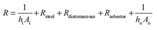
In the case of a composite cylinder the most convenient approach is again that of the electrical analogy; by using where x is thickness of a layer and Am is the logarithmic mean area for that layer.
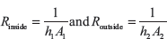
The film of fluid on the inside and outside surfaces can be treated as
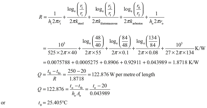
Example 7.5: A steel pipe of 80 mm bore and 8 mm wall thickness, carrying steam at 250°C, is insulated with 36 mm of a moulded high temperature diatomaceous earth covering. This covering is in turn insulated with 50 mm of asbestos felt. If the atmospheric temperature is 20°C, calculate the rate at which heat is lost by the steam per metre length of pipe. The heat transfer coefficients for the inside and outside surfaces are 525 and 27 W/m2K, respectively, and the thermal conductivity of steel, diatomaceous earth and asbestos felt are 55, 0.1 and 0.08 W/m K, respectively. Calculate also the temperature of the outside surface.
Solution:
Given: ri = 40mm; r1 = 48mm; r2 = 84mm; r0 = 134mm; h1 = 525 W/m2K; m2K
Now resistance of per unit length of pipe
Leave a Reply