14.7.1 Hartnell Governor
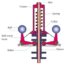
The Hartnell governor is shown in Figure 14.7(a). The two bell crank levers are used which can rotate about fulcrums O and O′. One end of both bell crank lever carries a ball and a roller at the other end of the arm. The rollers make contact with the sleeve. A helical spring is mounted on the spindle between frame and sleeve. With the rotation of the spindle, all these parts rotate.
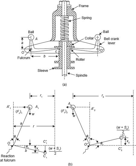
Figure 14.7 (a) Hartnell Governor and (b) Force Analysis of Hartnell Governor
With the increase in speed, the radius of rotation of the balls increases and the rollers lift the sleeve against the spring force. With the decrease in speed, the sleeve moves downwards. The movement of the sleeve is transferred to the throttle of the engine through linkages.
Let
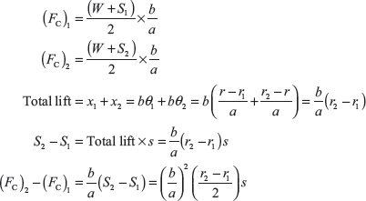
Considering the position of the ball at radius ‘r2’ as shown in Figure 14.7(b) and taking the moments of all the forces about O′.
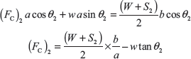
If θ1 and θ2 are small. Weight w is small in comparision to W and spring force S, w tan θ1 and w tan θ2 can be neglected.
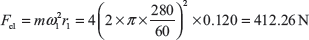
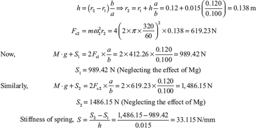
Example 14.5: A Hartnell governor having a central sleeve spring and two right angled bell crank levers moves between 280 and 320 rpm for a sleeve lift of 15 mm. The sleeve arms and the ball arms are 100 and 120 mm, respectively. The levers are pivoted at 120 mm from the governor axis and mass of each ball is 4 kg. The ball arms are parallel to the governor axis at the lowest equilibrium speed. Determine load on spring at lowest and highest speeds and stiffness of the spring.
Solution:
Let
S1 = Load on spring at lowest speed
S2 = Load on spring at highest speed
Since the ball arms are parallel to governor axis at the lowest speed, therefore, r = r1 = 120 mm
Let r2 is radius of rotation at N2 = 320 rpm.
14.7.2 Willson–Hartnell Governor
In this governor, balls are connected by a spring (in two parts) and one more spring is used in sleeve mechanism to adjust the radius of rotation of the balls as shown in Figure 14.8.
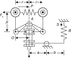
Figure 14.8 Willson–Hartnell Governor
Let
P = Tension in the main spring A
S = Tension in spring B
w = Weight of each ball
W = Weight of sleeve
sa = Stiffness of each ball spring A
sb = Stiffness in auxiliary spring B
FC = Centrifugal force on each ball
r = Radius of rotation of balls
Taking moment about O neglecting weight of ball, we get
Using 1 and 2 suffix for minimum and maximum equilibrium speed
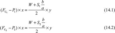
On subtraction, we get

When the radius of rotation increases from r1 to r2, the spring A extends by 2 (r2 − r1) and spring B extends by (r2 − r1) × ![]() .
.
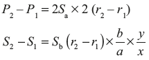
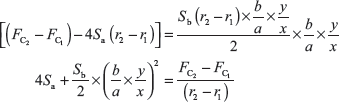
Substituting the value of P2 − P1 and S2 − S1 in Eq. (14.3)
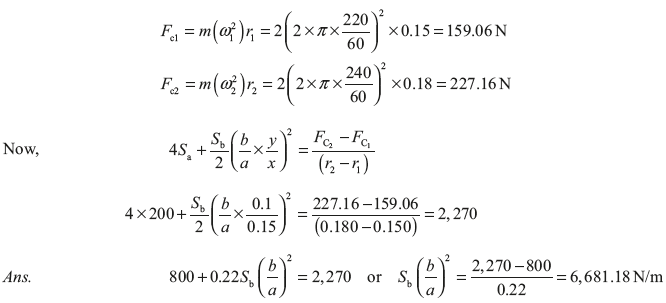
Example 14.6: A Wilson–Hartnell governor consists of balls of mass of 2 kg each, minimum and maximum radius of rotation 150 and 180 mm, respectively, minimum and maximum speed 220 and 240 rpm, respectively, length of ball arm of each bell crank lever 150 mm, length of the sleeve arm of each bell crank lever 100 mm, and combined stiffness of two ball springs 0.2 kN/m. Find the equivalent stiffness of the auxiliary spring referred to the sleeve.
Solution:
Let S be the equivalent stiffness of the auxiliary spring referred to the sleeve, ![]()
We know the centrifugal force at the minimum speed,
14.7.3 Hartung Governor
The Hartung governor is shown in Figure 14.9. In this governor, the vertical arms of the bell crank levers are fitted with spring balls which compress against the frame of the governor when the rollers at the end of horizontal arms press against the sleeve.

Figure 14.9 Hartung Governor
S = Spring force
FC = Centrifugal force
W = Weight of sleeve
x and y = Lengths of vertical and horizontal arms of bell crank lever, respectively.
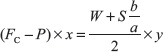
Taking moment about fulcrum O, we get

Example 14.7: In a Hartung type governor ball arm and sleeve arm length are 80 and 100 mm, respectively. The total travel of the sleeve is 15 mm. In the mid position each spring is compressed by 40 mm and radius of rotation of mass centre is 120 mm, each ball has a mass of 4 kg and spring has a stiffness of 10 kN/m in compression. The equivalent mass at governor sleeve is 15 kg. Neglecting the moment due to revolving masses and when the arms are inclined, determine the speed in the mid position.
Solution:

Leave a Reply