The removal of extra material from a metal surface by shearing or cutting action is known as machining or metal cutting. The cutting takes place along a plane, which is known as shear plane. There is a cutting zone; if it is examined carefully we find that the severe plastic deformation occurs in this zone due to compressive force applied by the sharp-edged cutting tool. The extra material due to this deformation flows over the tool surface, known as chip, and this shearing zone is known as primary shear zone.
During flow of chip on the rake surface of the cutting tool, the temperature of newly formed chip increases due to friction and it gets welded automatically on the rake surface. But, due to compressive force applied by newly formed chip (just after the welded chip) causes secondary shear of the welded chip, and this shear is known as secondary shear. In metal cutting the line generated by the cutting motion is called generatrix and the line formed by feed motion is called directrix.
19.2.1 Types of Chip Formation
Various types of chips, which are formed in various cutting conditions and type of machining, can be categorized as follows:
- Continuous chip.
- Discontinuous chip.
- Continuous Chip with built-up Edge

Figure 19.1 Types of Chip Formation in Metal Cutting
Continuous Chip: Continuous chip, as shown in Figure 19.1(a), is formed due to
- Machining of ductile materials.
- Small undercut thickness.
- High cutting speed.
- Large rake angle of the tool.
- Suitable cutting fluids.
Discontinuous Chip: Discontinuous chip, as shown in Figure 19.1 (b), is formed due to
- Machining of brittle work materials.
- Low cutting speed.
- Small rake angle.
- Large uncut chip thickness.
Continuous Chip with Built-up (BUP) Edge: Continuous chip with built-up edge, as shown in Figure 19.1 (c), is formed due to
- Large friction or stronger adhesion between chips and tool face.
- Low rake angle.
- Large uncut chip thickness.
19.3 GEOMETRY OF SINGLE POINT CUTTING TOOL
The different view of single point cutting tool is shown in Figure 19.2. According to ASA (American Standard Association) there are seven parameters of tool geometry as mentioned below as
αb, αs, βe, βs, θe, θs, R
where αb is the back rake angle; αs, side rake angle; βe, end clearance angle; βs, side clearance angle; θe, end cutting edge angle; θs, side cutting edge angle; R, nose radius.
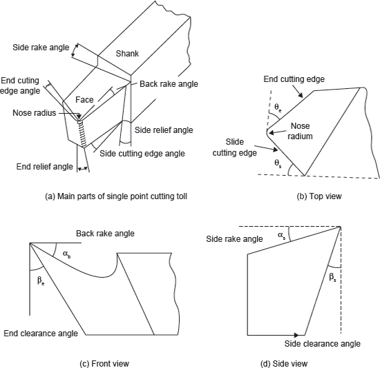
Figure 19.2 Nomenclature of Single Point Cutting Tool
Back Rake Angle and Side Rake Angle: Back rake angle is the angle between the face of the tool and a line parallel with base of the tool measured in a perpendicular plane through the side cutting edge. If the slope face is downward toward the nose, it is negative back rake angle and if it is upward toward nose, it is positive back rake angle. This angle helps in removing the chips away from the work piece. Generally, ceramic or brittle tool materials have negative back rake angle. It ranges from −5° to 15°.
Side rake angle is the angle between the base of the tool shank and the face of the tool measured in a plane perpendicular to the plane through the side cutting edge and right angle to the base. If the tool face is sloping upward towards the side cutting edge, side rake angle is positive and it is negative when it is sloping downward towards the side cutting edge. Positive side rake angle results in lower cutting force and low power consumption, and thus better cutting action. Negative side rake angle is used for rough cut and heavy duty applications. It ranges from −5° to 15°.
End Relief Angle and Side Relief Angle: The angle between the planes of the end flank immediately below the end cutting edge and line perpendicular to the base and right angle to the axis is known as end relief angle and the angle between the planes of the side flank immediately below the side cutting edge and line perpendicular to base along the axis is known as side relief angle. Relief angles are provided to ensure that no rubbing occurs between the work surface and flank surfaces of the tool. For general turning operations, they range from 5° to 15°.
End Cutting Edge Angle and Side Cutting Edge Angle: The angle between the plane along the end cutting edge and the plane perpendicular to the axis, both right angles to the base, is known as end cutting edge angle. End cutting edge angle provides a clearance to the trailing edge end of the cutting edge and machined surface to prevent the rubbing and drag action between them. Smaller value of end cutting edge angle generally uses less contact area with respect to the metal being cut. Larger end cutting edge angle results in vibration or chatter. It is limited to 5°.
The angle between the plane along the side cutting edge and the plane perpendicular to the axis, both right angles to the base, is known as side cutting edge angle. It prevents the shock of the cut at the tip of the tool. It can vary from 0° to 90°. On increasing the angle, thickness of the chip decreases but its width increases.
Nose Radius: The nose radius has a major influence on surface finish. A sharp point at the end of a tool leaves a groove on the path of cut. Increase in nose radius usually decreases tool wear and improves surface finish. Generally, for roughing largest nose radius is selected. A larger nose radius permits higher feed, but must be checked against any vibration tendencies.
19.4 ORTHOGONAL AND OBLIQUE METAL CUTTING
Orthogonal cutting is a machining process in which the cutting edge of the tool is kept perpendicular to the direction of the tool travel (Figure 19.3). But, in oblique cutting, the cutting edge of the tool is inclined at some acute angle to the direction of the tool travel. There are some fundamental differences in orthogonal and oblique cutting.
Differences Between Orthogonal and Oblique Cutting
| Orthogonal Cutting | Oblique Cutting |
|---|---|
| The cutting edge of the tool is perpendicular to the direction of the tool travel.The cutting edge clears the width of the workpiece on either end.The chip flows over the rake surface of the cutting tool in the direction perpendicular to the cutting edge. The shape of the chip coil is tight flat spiral.Only two components of the cutting force act on the cutting edge.Maximum chip thickness occurs at the middle.For same feed and depth of cut, the force which shears the metal acts on a smaller area and therefore, the heat developed per unit area due to friction along the tool work interface is more and tool life is less. | The cutting edge of the tool is inclined at some acute angle to the direction of the tool travel.The cutting edge may or may not clear the width of the workpiece on either end.The chip flows on the rake surface of the tool making an angle with the normal on the cutting edge. The chip flows sideways in a long curl.Three components of the forces mutually perpendicular act at the cutting edge.The maximum chip thickness may not occur at the middle.Force of cutting acts on longer area and therefore, the heat developed per unit area due to friction along the tool work interface is more and tool life is less. |

Figure 19.3 Schematic View of Orthogonal and Oblique Cutting
Leave a Reply