
In AC circuits, it is required to add or subtract the alternating quantities. In such cases, it should be proceed as follows:
6.19.1 Addition of Alternating Quantities
The given alternating quantities are represented as phasor, and then, they are added in the same manner as forces are added. Only phasors of the similar quantities are added, that is, either all the currents are added or all the voltages are added. Voltages and currents are never added with each other. For addition, the following methods are accomplished:
- Parallelogram method
- Method of components
- Parallelogram Method: This method is applied for the addition of two phasors at a time. The two quantities are represented in magnitude and direction (phasors) as the adjacent sides of a parallelogram. The diagonal of this parallelogram represents the magnitude of the resultant.Consider an AC parallel circuit having two branches, as shown in Figure 6.25, carrying a current of i1 and i2, respectively. Let the two currents be represented as follows: i1= Im1 sin ωt and i2 = Im2 sin (ωt + θ)
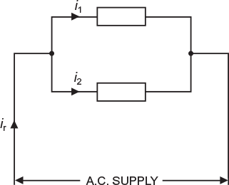 Fig. 6.25 AC current in parallel circuitsThe maximum values of the two currents Im1 and Im2 are represented as the two adjacent sides OA and OB, respectively, of a parallelogram OACB as shown in Figure 6.26. The current Im2 leads the current Im1 by an angle θ °. The maximum value of the resultant is say Imr represented by the diagonal OC of the parallelogram and leads the phasor Im1 by an angle ɸ.
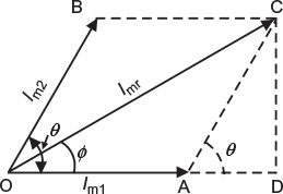 Fig. 6.26 Phasor representation (for finding resultant by parallelogram method)
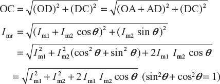 Phase angle,
 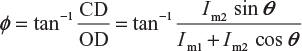 The instantaneous value of the resultant current is given by the relation; ir = Imr sin(ω × t + ɸ) as ɸ is positive.
 - Method of components: In this method, each phasor is resolved into horizontal and vertical components. The horizontal components are added algebraically to obtain the resultant horizontal component IXX. Similarly, vertical components are summed up algebraically to obtain the resultant vertical component IYY.Consider an AC parallel circuit consisting of three branches each carrying a current of i1, i2, and i3, respectively, as shown in Figure 6.27. Let the three currents be represented as follows: i1 = Im1 sin (ωt + θ1) i2 = Im2 sin ωt and i3 = Im3 sin (ωt − θ2)
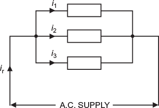 Fig. 6.27 AC current in parallel circuitThe maximum values of the three currents Im1, Im2, and Im3 are represented by the phasors as shown in Figure 6.28(a). The components are resolved horizontally and vertically.Algebraic sum of horizontal components IXX = Im1cosθ1 + Im2 + Im3cosθ2 Algebraic sum of vertical components IYY = Im1 sin θ1 + 0 − Im3 sin θ2 Maximum value of resultant components
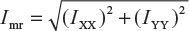 If ɸ is the phase difference (leading) between resultant current and horizontal axis as shown in Figure 6.28(b). Then,
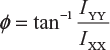 The instantaneous value of the resultant current is given by the relation; ir = Imr sin (ωt + ɸ) However, if IYY comes out to be negative, the angle of phase difference will be lagging (i.e., −ɸ). Then, the instantaneous value of the resultant current will be given by the relation ir = Imr sin (ωt − ɸ)
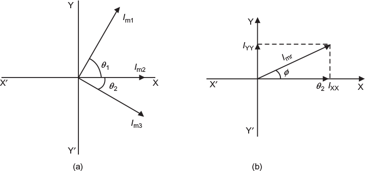 Fig. 6.28 (a) Phasor representation of three current (b) Finding resultant by component method
6.19.2 Subtraction of Alternating Quantities
The methods explained above (i.e., parallelogram method and method of components) are also applied for the subtraction of an alternating quantity. The only difference is that in this case, the phasor of the alternating quantity which is to be subtracted is reversed or represented 180° out of phase. Then it is added with the other alternating quantity (or quantities) as usual.
Calculate (i) the maximum value and (ii) the root-mean-square value of the following quantities:
(i) 40 sin ωt (ii) B sin (ωt − π/2) (iii) 10 sin ωt − 17.3 cosωt
Draw the vectors showing the phase difference with respect to A sin (ωt − π /6).
Solution:
The instantaneous value of an alternating quantity is given by the relation
i = Im sin ωt
- The given alternating quantity is 40 sin ωt∴ Maximum value = 40 (Ans.)RMS value = Max. value/
 = 40/ = 28.284 (Ans.)The vector lies on the horizontal axis as shown in Figure 6.29(a).
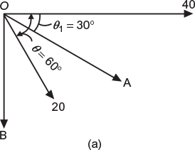 Fig. 6.29 (a) Phasor diagram as per data
 - The given alternating quantity is B sin (ωt − π/2)∴ Maximum value = B (Ans.)RMS value = B/(Ans.)The vector lags behind the horizontal axis by 90° as shown in Figure 6.29(b).
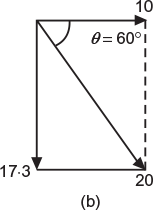 Fig. 6.29 (b) Resultant phasor diagram
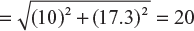
 - The given alternating quantity is 10 sin ωt − 17.3 cosωt. In fact, this quantity has two components displaced from each other by 90° as shown in Figure 6.29(a).Resultant maximum value
Let the phase angle of the resultant with the horizontal be θ °.
∴
tanθ = 17.3/10 = 1.73
or
θ = tan−1 1.73 = 60°
Hence, this vector lags behind the horizontal axis by 60° as shown in Figure 6.29(b). This vector is also represented in Figure 6.29(a).
The quantity A sin (ωt − π/6) makes as angle of lag, θ1 = π/6 = 30° with the horizontal as shown in Figure 6.29(a).
Considering phasor diagram shown in Figure 6.29(a);
The phase difference between first quantity (i.e., 40) and A = 30° (Ans.)
The phase difference between second quantity (i.e., B) and A = 60° (Ans.)
The phase difference between third quantity (i.e., 20) and A = 60° − 30° = 30° (Ans.)
Example 6.16
Two AC voltages are represented as follows:
ν1 (t) = 30 sin (314 t + 45°);
ν2 (t) = 60 sin (314 t + 60°)
Calculate the resultant υ(t) and express in the form:
υ(t) = Vm sin (314 t ± ɸ)
(U.P.T.U. 2003–2004)
Solution:
θ (t) = m × t + 0 = 1 × t
The phasor representation of the two voltages is shown in Figure 6.30.
ν1 (t) = 30 sin (314 t + 45°); ν2 (t) = 60 sin (314 t + 60°)
Resolving the vectors V1m and V2m horizontally and vertically, we get,
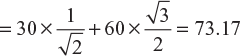
Σ Vxx = 30 cos 45° + 60 cos 60°
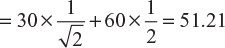
Σ Vyy = 30 sin 45° + 60 sin 60°
Maximum value of resultant voltage,
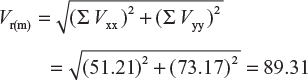
Phase angle, 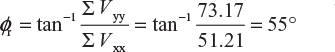
Resultant voltage, υ(t) = Vr(m) sin (ωt + ɸr) = 89.31 sin (314 t + 55°) (Ans.)
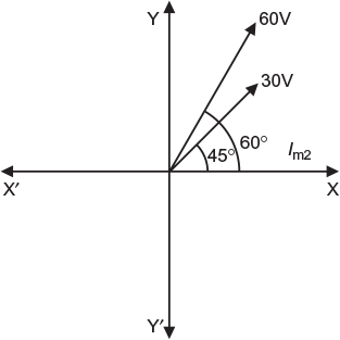
Fig. 6.30 Phasor diagram as per data
Example 6.17
Draw a phasor diagram showing the following voltages.
ν1 = 100 sin 500 t;
ν2 = 200 sin (500 t + π /3)
ν3 = − 50 cos 500 t;
ν4 = 150 sin (500 t − π /4)
Find RMS value of resultant voltage.
(U.P.T.U. 2005–2006)
Solution:
ν1 = 100 sin 500 t;
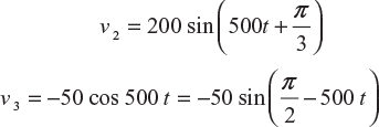
= 50 sin (500 t − π/2)
ν4 = 150 sin (150 t − π/4)
All the four voltages are shown vectorially in Figure 6.31.
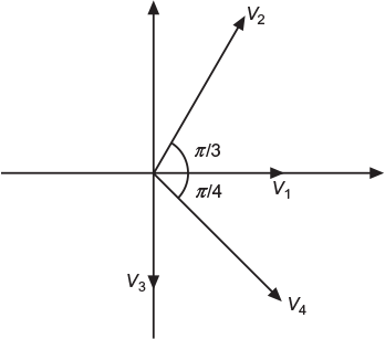
Fig. 6.31 Phasor diagram as per data
Resolving the phasors in horizontal axis
= 100 × 1 + 200 × 0.5 + 50 × 0 + 150 × 0.707
= 306.05 V
Resolving the phasors in vertical axis

= 100 × 0 + 200 × 0.866 − 50 × 1 − 150 × 0.707
= 17.15 V
Maximum value of resultant voltage

RMS value of resultant voltage, ![]()
Example 6.18
Three sinusoidal voltages acting in series are given by
ν1 = 10sin 440t; ν2 = 10![]() sin (440t – 45°); ν3 = 20 cos 440t
sin (440t – 45°); ν3 = 20 cos 440t
- an expression for the resultant voltage,
- the frequency and rms value of the resultant voltage.(U.P.T.U., February 2001)
Solution:
Here,
υ1 = 10 sin 440 t
υ2 = 10![]() sin (440t – 45°);
sin (440t – 45°);
υ3 = 20 cos 440t 
All the three voltages are shown vectorially in Figure 6.32.
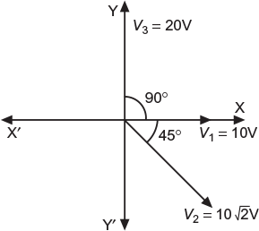
Fig. 6.32 Phasor diagram as per data
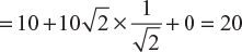
Resolving voltage along X-axis and Y-axis, we get,
Vxx = 10cos 0° + 10![]() cos(–45°) + 20 cos 90°
cos(–45°) + 20 cos 90°
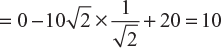
Vyy = 10sin 0° + 10![]() cos(–45°) + 20 sin 90°
cos(–45°) + 20 sin 90°
Maximum value of resultant voltage,

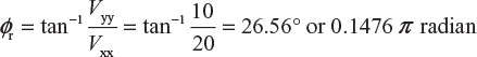
- Expression for resultant voltage, υr = 22.36 sin (440 t + 0.1476 π) (Ans.)
- Frequency,
RMS value of resultant voltage, ![]()
Example 6.19
Three voltages represented by e1 = 10 sin wt, e2 = 15 sin (ωt + π/4), and e3 = 20 cos (ωt − π/6) act together in a circuit. Find an expression for the resulting voltage.
Solution:
The three voltages are represented vectorially in Figure 6.33. The third voltage (20 V) makes an angle of lag of 30° with the vertical.
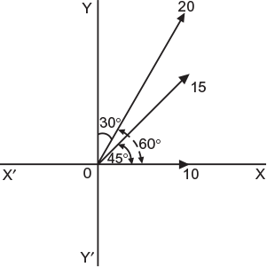
Fig. 6.33 Phasor diagram as per data
Resolving the components along X-axis
EXX = 10 + 15 cos 45° + 20 cos 60°
= 10 + 15 × 0.707 + 20 × 0.5 = 30.607 V
Resolving the components along Y-axis,
EYY = 0 + 15 sin 45° + 20 sin 60°
= 0 + 15 × 0.707 + 20 × 0.866 = 27.927 V
Maximum value of resultant voltage,

Let ɸ be the angle which the resultant voltage makes with X-axis
∴
ɸ = tan−1 10.9124 = 42.38°
∴ Expression for the resultant voltage,
er = Emr sin (ωt + ɸ) = 41.433 sin (ωt + 42.38°) (Ans.)
Example 6.20
Two currents i1 and i2 are given by the expressions: (i) 40 sin (314 t + π/6) (ii) 20 sin (314 t − π/3)
Find i1 − i2 and express the answer in the same form as individual currents. Find also the rms value and frequency of the resultant current.
Solution:
The two currents are represented by phasors as shown in Figure 6.34. Since current i2 is to be subtracted from i1, reverse the phasor Im2 (dotted phasor) and find its vector sum with Im1.
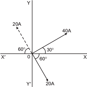
Fig. 6.34 Phasor diagram as per data
Resolving the components along X-axis;
IXX = 40 cos 30° − 20 cos 60°
= 40 × 0.866 − 20 × 0.5 = 24.64 A
Resolving the components along Y-axis;
IYY = 40 sin 30° + 20 sin 60°
= 40 × 0.5 + 20 × 0.866 = 37.32 A
Maximum value of resultant current,

= 44.72 A
Let ɸ be the angle which resultant current makes with X-axis
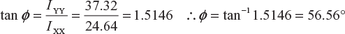
∴ Expression for the resultant current,
ir = Imr sin (ωt + ɸ) = 44.72 sin (314 t + 56.56°) (Ans.)
or
ir = 44.72 sin (314 × t + 0.9872) [where ɸ is in radians]
RMS value of resultant current,
From the equation, ω = 314 or 2 πf = 314
∴ Frequency, f = 314/2 π = 50 Hz (Ans.)
Example 6.21
The instantaneous values of two alternating voltages are represented by υ1 = 60 sin θ and υ2 = 40 sin (θ − π/3). Derive expression for the instantaneous values of (i) the sum and (ii) the difference of these voltages.
(U.P.T.U. July, 2002)
Solution:
Here,
υ1 = 60 sin θ and 
The two voltages are shown vectorially in Figure 6.35(a)
- When the two voltages are to be added, Vxx = V1 cos 0° + V2 cos (−60°) = 60 × 1 + 40 × 0.5 = 80 VVyy = V1 sin 0° + 40 sin (−60°) = 60 × 0 + 40 × (−0.866) = −34.64 V
 Phase angle,
 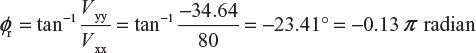 Expression for the instantaneous value of the resultant voltage, Vr = Vr(m) sin (θ − ɸr) = 87.2 sin (θ − 0.13 π) volt (Ans.)
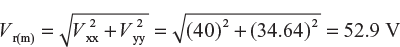
 - When one of the voltage (say V2) is to be subtracted from the other (say V1)The vector representing V2 is reversed as shown in Figure 6.35(b) and then added to V1. Vxx = V1cos θ ° − V2 sin (−60°) = 60 × 1 −40 × 0.5 = 40 VVyy = V1 sin θ °− V2 sin (−60°) = 60 × 0 −40 × (−0.866) = 34.64 V
 Phase angle,
 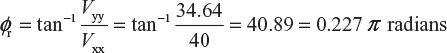 Expression for the instantaneous value of resultant voltage, Vr = Vr(m) sin (θ + ɸr) = 52.9 sin (θ + 0.227 π) (Ans.)
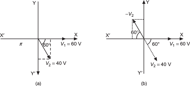
Fig. 6.35 (a) Phasor diagram for addition (b) Phasor diagram for subtraction
Leave a Reply