
A voltage that changes its polarity and magnitude at regular intervals of time is called an ‘alternating voltage’.
When an alternating voltage source is connected across a load resistor R as shown in Figure 6.1, the current flows through it in one direction and then in opposite direction when the polarity is reversed.
Figure 6.1(c) shows the wave shape of the source voltage (representing the variation of voltage with respect to time) and current flowing through the circuit (i.e., load resistor R).
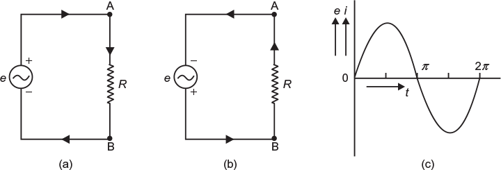
Fig. 6.1 Alternating voltage and current (a) AC voltage applied across resistor, flow of current during first half cycle (b) AC voltage applied across resistor, flow of current during next half cycle
6.2.1 Wave Form
As shown in graph (Fig. 6.2), an alternating voltage or current changes with respect to time is known as ‘wave form or wave shape’. While plotting a graph, usually the instantaneous values of the alternating quantities are taken along Y-axis and time along X-axis. The alternating voltage or current may vary in different manner, as shown in Figure 6.2, and accordingly, their wave shapes are named in different ways such as irregular wave, triangular wave, square wave, periodic wave, sawtooth wave, sine wave, etc.
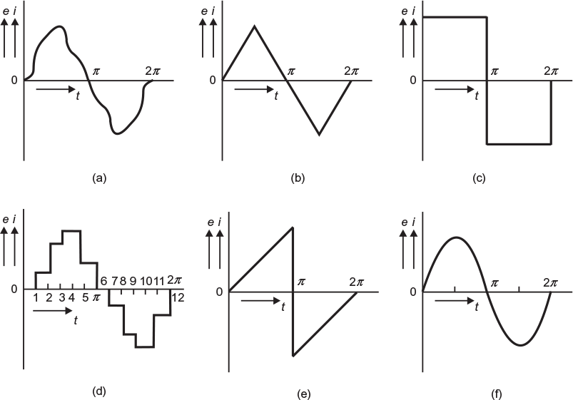
Fig. 6.2 AC wave shapes (a) General ac wave (b) Triangular wave (c) Square wave (d) Periodic wave (e) Triangular/saw tooth wave (f) Sinusoidal wave
Leave a Reply