
The function of a commutator in DC motors is to reverse the direction of flow of current in each armature conductor when it passes through the MNA to obtain continuous torque.
11.16 BACK EMF
It has been seen that when current is supplied to the armature conductors, as shown in Figure 11.36(a), placed in the main magnetic field, torque is developed; thus, the armature rotates. Simultaneously, the armature conductors cut across the magnetic field and an emf is induced in these conductors. The direction of this induced emf in the armature conductors is determined by Fleming’s right-hand rule and is marked in Figure 11.36(b).
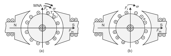
Fig. 11.36 (a) Flow of rotor current due to applied voltage (b) Direction of induced emf in rotor conductors
It can be seen that the direction of this induced emf is opposite to the applied voltage. That is why this induced emf is called back emf (Eb). The magnitude of this induced emf is given by the relation:
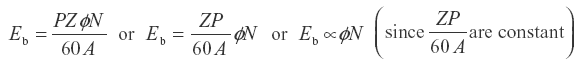
Further,  shows that speed of motor is inversely proportional to magnetic field or flux.
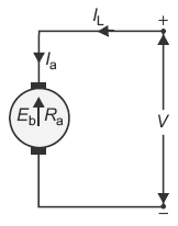
Fig. 11.37 Conventional circuit diagram of a DC motor
A simple conventional circuit diagram of the machine working as motor is shown in Figure 11.37. In this case, the supply voltage is always greater than the induced or back emf (i.e., V > Eb). Therefore, current is always supplied to the motor from the mains and the relation among the various quantities will be Eb = V − Ia Ra.
Leave a Reply