The magnetic flux that does not follow the intended path in a magnetic circuit is called leakage flux.
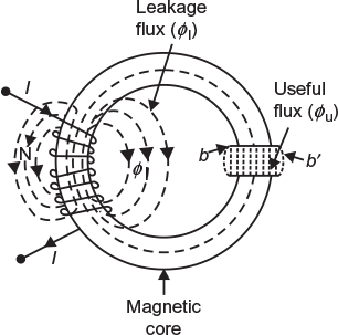
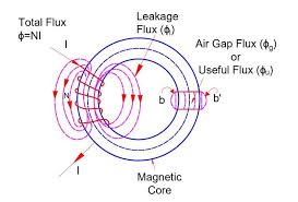
Fig. 5.7 Magnetic circuit with leakage flux
When some current is passed through a solenoid, as shown in Figure 5.7, magnetic flux is produced by it. Most of this flux is set up in the magnetic core and passes through the air gap (an intended path). This flux is known as useful flux ɸu. However, some of the flux is just set up around the coil and is not utilised for any work. This flux is called leakage flux ɸl.
Total flux produced by the solenoid.
ɸ = ɸu + ɸ l
Leakage co-efficient or leakage factor: the ratio of total flux (μ) produced by the solenoid to the useful flux (ɸ) produced by the solenoid to the useful flux (ɸu) set up in the air gap is known as leakage co-efficient. It is generally represented by letter ‘λ’.
Therefore, leakage co-efficient, 
5.9.1 Fringing
It may be seen in Figure 5.7 that the useful flux when sets up in the air gap, it tends to bulge outwards at b and b´ since the magnetic lines set up in the same direction repel each other. This increases the effective area in the air gap and decreases the flux density. This effect is known as fringing. The fringing is directly proportional to the length of the air gap.
Example 5.1
An iron ring of 400 cm mean circumference is made from round iron of cross section 20 cm2. Its permeability is 500. If it is wound with 400 turns, what current would be required to produce a flux of 0.001 Wb?
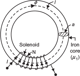
Fig. 5.8 Given magnetic circuit
Solution:
The magnetic circuit is shown in Figure 5.8.
Mean length of magnetic path, lm = 400 cm = 4 m
Area of X-section of iron ring, a = 20 × 10−4 m2
Absolute permeability, μ0 = 4π × 10−7
Now, mmf = flux × reluctance
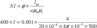
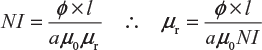
∴
Current, ![]()
Current, I = 7.958
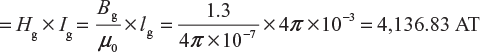
An electromagnet has an air gap of 4 mm and flux density in the gap is 1.3 Wb/m2. Determine the AT for the gap.
(UPTU 2006–2007)
Solution:
Here, lg = 4 mm = 0.4 cm = 4 × 10⁻³ m; Bg = 1.3 Wb/m2
Ampere turns required for the gap
Example 5.3
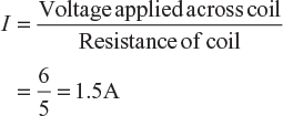
A coil of insulated wire of 500 turns and of resistance 4 Ω is closely wound on an iron ring. The ring has a mean diameter of 0.25 m and a uniform cross-sectional area of 700 mm2. Calculate the total flux in the ring when a DC supply of 6 V is applied to the ends of the winding. Assume a relative permeability of 550.
(UPTU July 2002)
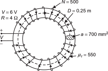
Fig. 5.9 Given magnetic circuit
Solution:
Mean length of the iron ring,
l = π D = π × 0.25 = 0.25 π m
Area of cross section,
α = 700 mm2 = 700 × 10−6 m2
Current flowing through the coil,
Total flux in the ring, 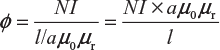
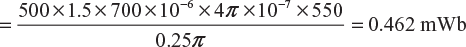
Example 5.4
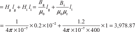
What are the similarities between electrical circuits and magnetic circuits? An iron ring of mean length 50 cm and relative permeability 300 has an air gap of 1 mm. If the ring is provided with winding of 200 turns and a current of 1 A is allowed to flow through, find the flux density across the air gap.
(UPTU June 2001)
Solution:
Here, li = 50 cm = 0.5 m; μr = 300; lg = 1 mm = 0.001 m; N = 200 turns; I = 1 A
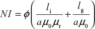
Ampere turns required for air gap ![]()
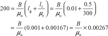
Ampere turns required for iron ring 
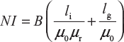
total AT required 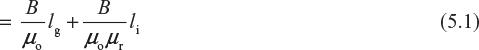
Ampere turns provided by the coil = NI = 200 × 1 = 200 (5.2)
Equating Equations (5.1) and (5.2), we get
or
or
Flux density, ![]()
Example 5.5
A coil of 1,000 turns is wound on a laminated core of steel having a cross section of 5 cm2. The core has an air gap of 2 mm cut at right angle. What value of current is required to have an air-gap flux density of 0.5 T? The permeability of steel may be taken as infinity. Determine the coil inductance.
(UPTU December 2003)
Solution:
Here, N = 1,000 turns; a = 5 cm2 = 5 × 10⁻⁴ m2;
lg = 2 mm = 2 × 10⁻³ m; B = 0.5 T; μr = ∞
Total AT required,
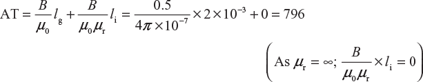
Current required,
Inductance of coil,
= 0.314 H
Example 5.6
A flux density of 1.2 Wb/m2 is required in 2-mm air gap of an electromagnet having an iron path 1 m long. Calculate the magnetising force and current required if the electromagnet has 1,273 turns. Assume relative permeability of iron to be 1,500.
(PTU)
Solution:
| Flux density, | B = 1.2 Wb/m2 |
| Relative permeability of iron, | µr = 1,500 |
| Number of turns, | N = 1,273 |
| Length of iron path, | li = 1 m |
| Length of air gap, | lg = 2 mm = 0.002 m |
Magnetising force for air gap, ![]()
AT required for iron path = Hili = 636.6 × 1 = 636.6
AT required for air gap = Hglg = 954,900 × 0.002 = 1,909.8
Total AT = 636.6 + 1,909.8 = 2,546.4
Current required, ![]()
Example 5.7
Estimate the number of AT necessary to produce a flux of 1,00,000 lines round an iron ring of 6 cm2 cross section and 20 cm mean diameter having an air gap 2 mm wide across it. The permeability of the iron may be taken as 1,200. Neglect the leakage flux outside the 2-mm air gap.
(PTU)
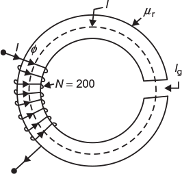
Fig. 5.10 Magnetic circuit with air-gap
Solution:
The magnetic circuit is shown in Figure 5.10.
Area of cross section of the ring, a = 6 cm2 = 6 × 10⁻⁴ m2
Mean diameter of the ring, Dm = 20 cm = 0.2 m
Length of air gap, lg = 2 mm = 2 × 10⁻³ m
Flux set up in the ring, ɸ = 100,000 lines
= 100,000 × 10−8 = 0.001 Wb
Relative permeability of iron, μr = 1,200
Mean length of ring, lm = π D = π × 0.2
= 0.6283 m
Length of air gap, lg = 0.002 m
Length of iron path, li = 0.6283 − 0.002
= 0.6263 m
Now, mmf = flux × reluctance
Ampere turns required for iron path,
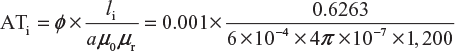
= 692.21 AT
Ampere turns required for air gap,
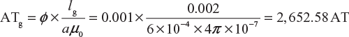
Total AT required to produce the given flux
= ATi + ATg = 692.21 + 2,652.58 = 3,344.79 AT
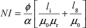
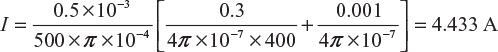
A wrought iron bar 30 cm long and 2 cm in diameter is bent into a circular shape, as given in Figure 5.11. It is then wound with 500 turns of wire. Calculate the current required to produce a flux of 0.5 mWb in magnetic circuit with an air gap of 1 mm; μr (iron) = 4,000 (assume constant).
(UPTU 2004–2005)
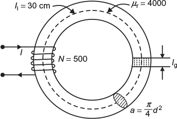
Fig. 5.11 Magnetic circuit with air-gap
Solution:
Here, Ii = 30 cm = 0.3 m;
Diameter, d = 2 cm
∴
Area, ![]()
= π ×10−4 m2
ɸ = 0.5 mWb = 0.5 × 10⁻³ Wb
N = 500 turns
Example 5.9
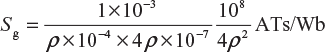
A circular ring 20 cm in diameter has an air gap 1 mm wide cut in it. The area of a cross section of the ring is 3.6 cm2. Calculate the value of DC needed in a coil of 1,000 turns uniformly wound round the ring to create a flux of 0.5 mWb in the air gap. Neglect fringing and assume relative permeability for iron as 650.
(UPTU 2006–2007)
solution:
| Here, area of cross section of the ring, | a = 3.6 cm2 = 3.6 × 10⁻⁴ m2 |
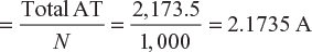
| Number of turns of the coil, | N = 1,000 |
| Flux set up, | ɸ = 0.5 mWb = 0.5 × 10⁻³ Wb |
| Relative permeability of iron, | µr = 650 |
| Length of air gap, | lg = 1 mm = 1 × 10⁻³ m |
Mean diameter of ring = 20 cm = 20 × 10−2 m
∴ Length of iron path li = ρD = ρ × 20 × 10−2 m = 62.83 × 10⁻⁴ m
Reluctance of iron path 
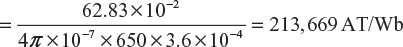
AT required for iron path = 0.5 × 10−3 × 213,669 = 1,068.3 AT
Reluctance of air gap 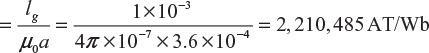
AT required for air gap = 0.5 × 10−3 × 2,210,485 = 1,105.2 AT
Total AT = (AT)i + (AT)gap = 1,068.3 + 1,105.2 = 2,173.5 AT
Current I
Example 5.10
A coil is wound uniformly with 300 turns over a steel ring of relative permeability 900 having a mean diameter of 20 cm. The steel ring is made of bar having circular cross section of diameter 2 cm. If the coil has a resistance of 50 Ω and is connected to 250 V DC supply, calculate the mmf of the coil, the field intensity in the ring, reluctance of the magnetic path, total flux, and permeance of the ring.
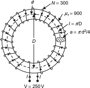
Fig. 5.12 Given magnetic circuit
Solution:
The magnetic circuit is shown in Figure 5.12.
Current through the coil, ![]()
mmf of the coil = NI = 300 × 5 = 1,500 AT
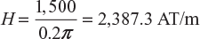
Field intensity ![]()
where
l = π D = 0.2π m
Reluctance of the magnetic path, ![]()
where
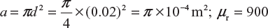
S = 0.2π /π × 10−4 × 4π × 10−7 × 900 = 17.684 × 10⁵ AT/Wb
Total flux,
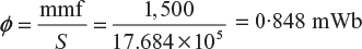
Permeance = 1/S = 1/17.684 × 105 = 5.655 × 10⁻⁷ Wb/AT
Example 5.11
Calculate the relative permeability of an iron ring when the exciting current taken by the 600 turn coil is 1.2 A and the total flux produced is 1 mWb. The mean circumference of the ring is 0.5 m and the area of cross section is 10 cm2.
Solution:
where N = 600 turns; I = 1.2 A; ɸ = 1 mWb = 1 × 10⁻³ Wb; l = 0.5 m;
a = 10 cm2 = 10 × 10−4 m2
Therefore, ![]()
Example 5.12
An iron ring of mean length 1 m has an air gap of 1 mm and a winding of 200 turns. If the relative permeability of iron is 500 when a current of 1 A flows through the coil, find the flux density.
(PTU)
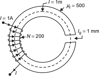
Fig. 5.13 Magnetic circuit with air-gap
Solution:
The magnetic circuit is shown in Figure 5.13.
Now, mmf = flux × reluctance
or
where N = 200 turns; I = 1 A; µr = 500
lg = 1 mm = 0.001 m;
li = (1 − 0.001) = 0.999 m
Therefore, 200 × 1 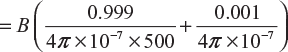
or
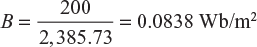
Example 5.13
A rectangular a magnetic core shown in Figure 5.14 (a) has square cross section of area 16 cm2. An air gap of 2 mm is cut across one of its limbs. Find the exciting current needed in the coil having 1,000 turns wound on the core to create an air-gap flux of 4 mWb. The relative permeability of the core is 2,000.
(UPTU February 2002)
Solution:
Here, area of x-section, a = 16 cm2 = 16 × 10−4 m2; lg = 2 mm = 2 × 10⁻³
Number of turns, N = 1,000; flux, ɸ = 4 mWb = 4 × 10⁻³ Wb; µr = 2,000
Flux density required, ![]()
Each side of the cross section ![]()
Length of iron path, 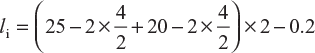
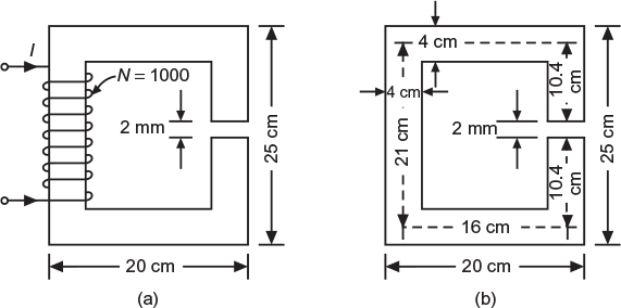
Fig. 5.14 Given magnetic circuit
= 73.8 cm = 0.738 m
Total AT required 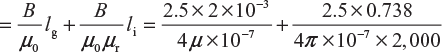
= 3,979 + 734 = 4,713
Exciting current required, ![]()
Example 5.14
An iron ring of 10 cm2 area has a mean circumference of 100 cm. It has a saw cut of 0.2 cm wide. A flux of 1 mWb is required in the air gap. The leakage factor is 1.2. The flux density of iron for relative permeability 400 is 1.2 Wb/m2. Calculate the number of AT required.
Solution:
Flux density in air gap, ![]()
Flux in iron ring, ɸi = l × ɸg (where λ = leakage factor)
= 1.2 × 1 × 10−3 = 1.2 × 10⁻³ Wb
Flux density in iron ring,
Total AT required
Example 5.15
A steel ring with a mean radius of 10 cm and of circular cross section 1 cm in radius has an air gap of 1 mm length. It is wound uniformly with 500 turn![]() s of wire carrying current of 3 A. Neglect magnetic leakage. The air gap takes 60% of the total mmf Find the total reluctance.
s of wire carrying current of 3 A. Neglect magnetic leakage. The air gap takes 60% of the total mmf Find the total reluctance.
Total mmf = NI = 500 × 3 = 1,500 AT
mmf for air gap = 60% of total mmf = 0.6 × 1,500 = 900 AT
Reluctance of air gap, 
where lg = 1 mm = 1 × 10⁻³ m; a = ρ × (0.01)2 = ρ× 10−4 m2;
Therefore,
Flux in the air gap, ![]()
mmf for iron = total mmf − air mmf = 1,500 − 900 = 600 AT
Flux in the iron ring, ɸi = ɸg = 36π2 ×10⁻⁶ Wb (since there is no magnetic leakage)
Reluctance of iron ring, 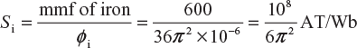
Total reluctance, 
= 4.22 × 10⁶ AT/Wb
Leave a Reply