
The region around the magnet where its poles exhibit a force of attraction or repulsion is called magnetic field. The existence of the magnetic field at a point around the magnet can also be determined by placing a magnetic needle at that point, as shown in Figure 5.1. Although magnetic lines of force have no real existence and are purely imaginary, yet their concept is very useful to understand various magnetic effects. It is assumed (because of their effects) that the magnetic lines of force possess the following important properties:
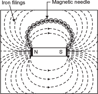
Fig. 5.1 Magnetic lines of force around a bar magnet
- The direction of magnetic lines of force is from N-pole to the S-pole outside the magnet. However, inside the magnet, their direction is from S-pole to N-pole.
- They form a closed loop.
- Their tendency is to follow the least reluctance path.
- They act like stretched cords, always trying to shorten themselves.
- They never intersect each other.
- They repel each other when they are parallel and are in the same direction.
- They remain unaffected by non-magnetic materials.
5.3 MAGNETIC CIRCUIT AND ITS ANALYSIS
The closed path followed by magnetic flux is called a magnetic circuit. A magnetic circuit usually consists of magnetic materials having high permeability (e.g., iron, soft steel, etc.). In this circuit, magnetic flux starts from a point and finishes at the same point after completing its path.
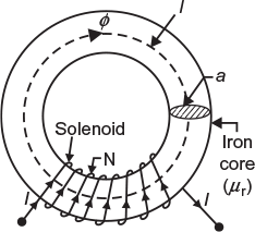
Fig. 5.2 Magnetic circuit
Figure 5.2 shows a solenoid having N turns wound on an iron core (ring). When current I ampere is passed through the solenoid, magnetic flux ɸ Wb is set up in the core.
Let l = mean length of magnetic circuit in m;
a = area of cross-section of core in m2;
μr = relative permeability of core material.
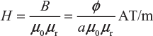
Flux density in the core material, ![]()
Magnetising force in the core material
According to work law, the work done in moving a unit pole once round the magnetic circuit (or path) is equal to the AT enclosed by the magnetic circuit.
Therefore,
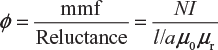
Hl = NI or 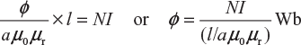
This expression reveals that the amount of flux set up in the core is
- directly proportional to N and I, that is, NI called magneto-motive force (mmf). It shows that the flux increases if either of the two increases and vice versa.
- inversely proportional to (l/a µoµr) called reluctance of the magnetic path. In fact, reluctance is the opposition offered to the magnetic flux by the magnetic path. The lower is the reluctance, the higher will be the flux and vice versa.
Thus,
It may be noted that the abovementioned expression has a strong resemblance to Ohm’s law for electric current (I = emf/resistance). The mmf is analogous to emf in electric circuit, reluctance is analogous to resistance, and flux is analogous to current. Because of this similarity, the above-mentioned expression is sometimes referred to as Ohm’s law of magnetic circuits.
5.4 IMPORTANT TERMS
Generally, while studying magnetic circuits, we come across the following terms:
- Magnetic field: The region around a magnet where its poles exhibit a force of attraction or repulsion is called magnetic field.
- Magnetic flux (ɸ): The amount of magnetic lines of force set up in a magnetic circuit is called magnetic flux. Its unit is weber (Wb). It is analogous to electric current, I, in electric circuit.The magnetic flux density at a point is the flux per unit area at right angles to the flux at that point.Generally, it is represented by letter ‘B’. Its unit is Wb/m2 or Tesla, that is,
- Permeability: The ability of a material to conduct magnetic lines of force through it is called the permeability of that material.It is generally represented by μ (mu, a Greek letter). The greater the permeability of a material, the greater is its conductivity for the magnetic lines of force and vice versa. The permeability of air or vacuum is the poorest and is represented as μ0 (where μ0 = 4 π × 10−7 H/m).
- Relative permeability: The absolute (or actual) permeability μ of a magnetic material is much greater than absolute permeability of air μ0. The relative permeability of a magnetic material is given in comparison with air or vacuum.Hence, the ratio of the permeability of material μ to the permeability of air or vacuum μ0 is called the relative permeability μr of the material.Therefore,
 Obviously, the relative permeability of air would be μ0 μr = 1. The value of relative permeability of all the non-magnetic materials is also 1. However, its value is as high as 8,000 for soft iron, whereas its value for Mu metal (iron 22% and nickel 78%) is as high as 120,000.
 - Magnetic field intensity: The force acting on a unit north pole (1 Wb) when placed at a point in the magnetic field is called the magnetic intensity of the field at that point. It is denoted by H. In magnetic circuits, it is defined as mmf per unit length of the magnetic path. It is denoted by H, and mathematically, it can be given as
- Magneto-motive force (mmf): The magnetic pressure that sets up or tends to set up magnetic flux in a magnetic circuit is called magneto-motive force. As per work law, it may be defined as the work done in moving a unit magnetic pole (1 Wb) once round the magnetic circuit is called mmf. In general, mmf = NI ampere turns (or AT) It is analogous to emf in an electric circuit.
- Reluctance (S): The opposition offered to the magnetic flux by a magnetic circuit is called its reluctance.It depends upon length (l), area of cross section (a), and permeability (µ = µ0µr)the material that makes up the magnetic circuit. It is measured in AT/Wb.Reluctance,
 It is analogous to resistance in an electric circuit.
 - Permeance: It is a measure of the ease with which flux can be set up in the material. It is just reciprocal of reluctance of the material and is measured in Wb/AT or Henry.
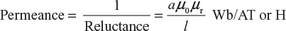 It is analogous to conductance in an electric circuit.
 - Reluctivity: It is specific reluctance and analogous to resistivityin an electric circuit.
5.5 COMPARISON BETWEEN MAGNETIC AND ELECTRIC CIRCUITS
Although magnetic and electric circuits have many points of similarity, but still they are not analogous in all respects. A comparison of the two circuits is given in Table 5.1.
Table 5.1 Comparison between Magnetic and Electric Circuits
| S.No. | Magnetic circuits | Electrical Circuits |
|---|---|---|
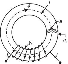 Fig. 5.3 Magnetic circuit Fig. 5.3 Magnetic circuit | 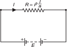 Fig. 5.4 Electric circuit Fig. 5.4 Electric circuit |
| Dissimilarities | ||
|---|---|---|
| 1. | In fact, the magnetic flux does not flow but it sets up in the magnetic circuit (basically, molecular poles are aligned). | The electric current (electrons) actually flows in an electric circuit. |
| 2. | For magnetic flux, there is no perfect insulator. It can be set up even in the non-magnetic materials such as air, rubber, and glass with reasonable mmf | For electric current, there are large number of perfect insulators such as glass, air, and rubber that do not allow it to follow through them under normal conditions. |
| 3. | The reluctance (S) of a magnetic circuit is not constant rather it varies with the value of B. It is because the value of µr changes considerably with the change in B. | The resistance (R) of an electric circuit is almost constant as its value depends upon the value of r , which is almost constant. However, the value of r and R may vary slightly if temperature changes. |
| 4. | Once the magnetic flux is set up in a magnetic circuit, no energy is expanded. However, a small amount of energy is required at the start to create flux in the circuit. | Energy is expanded continuously, so long as the current flows through an electric circuit. This energy is dissipated in the form of heat. |
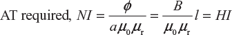
5.6 Ampere Turns calculations
In a magnetic circuit, flux produced is given as
or
5.7 SERIES MAGNETIC CIRCUITS
A magnetic circuit that has a number of parts of different dimensions and materials carrying the same magnetic field is called a series magnetic circuit. Such series magnetic circuit (composite circuit) is shown in Figure 5.5.
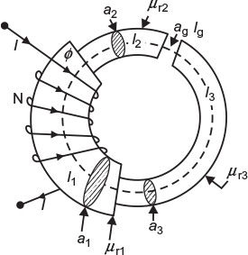
Fig. 5.5 Series magnetic circuit
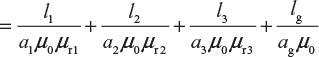
Total reluctance of the magnetic circuit,
S = S1 + S2+ S3 + Sg
Total mmf = ɸS
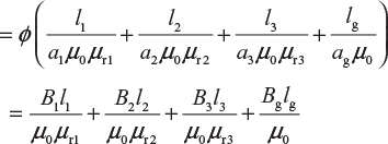
= H1l1 + H2l2 + H3l3 + Hglg
5.8 PARALLEL MAGNETIC CIRCUITS
A magnetic circuit that has two or more than two paths for the magnetic flux is called a parallel magnetic circuit. Its behaviour can be just compared to a parallel electric circuit.
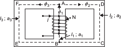
Fig. 5.6 Parallel magnetic circuit
Figure 5.6 shows a parallel magnetic circuit. A current-carrying coil is wound on the central limb AB. This coil sets up a magnetic flux ɸ1 in the central limb that is further divided into two paths, that is, path ADCB that carries flux ɸ2 and path AFEB that carries flux ɸ3.
It is clear that ɸ1 = ɸ2 + ɸ3
The two magnetic paths ADCB and AFEB are in parallel. The AT required for this parallel circuit is equal to the AT required for any one of the paths.
If
S1 = reluctance of path BA, that is, l1/a1 μ0 μr1
S2 = reluctance of path ADCB, that is, l2/a2 μ0 μr2
S3 = reluctance of path AFEB, that is, l3/a3 μ0 μr3
Therefore, total mmf required = mmf required for path BA mmf required path ADCB or path AFEB
Total mmf or AT = ɸ1 S1 + ɸ2 S2 = ɸ1 S1 + ɸ3 S3
5.9 LEAKAGE FLUX
The magnetic flux that does not follow the intended path in a magnetic circuit is called leakage flux.
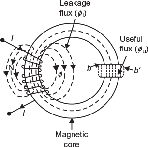
Fig. 5.7 Magnetic circuit with leakage flux
When some current is passed through a solenoid, as shown in Figure 5.7, magnetic flux is produced by it. Most of this flux is set up in the magnetic core and passes through the air gap (an intended path). This flux is known as useful flux ɸu. However, some of the flux is just set up around the coil and is not utilised for any work. This flux is called leakage flux ɸl.
Total flux produced by the solenoid.
ɸ = ɸu + ɸ l
Leakage co-efficient or leakage factor: the ratio of total flux (μ) produced by the solenoid to the useful flux (ɸ) produced by the solenoid to the useful flux (ɸu) set up in the air gap is known as leakage co-efficient. It is generally represented by letter ‘λ’.
Therefore, leakage co-efficient
Leave a Reply