
This value of flux density ‘ob’ retained by the magnetic material is called residual magnetism and the power of retaining this residual magnetism is called retentivity of the material. To demagnetise the magnetic ring, the magnetising force H is reversed by reversing the direction of flow of current in the solenoid. This is achieved by changing the position of double pole, double throw switch (i.e., position ‘2’). When H is increased in reverse direction, the flux density starts decreasing and becomes zero and curve follows the path bc. Thus, residual magnetism of the magnetic material is removed by applying magnetising force oc in opposite direction.
5.11.2 Coercive Force
This value of magnetising force oc required to remove the residual magnetism is called coercive force. To complete the loop, the magnetising force H is increased further in reverse direction till saturation reaches (point ‘d’) and the curve follows the path cd. Again H is reduced to zero and the curve follows the path de, where oe represents the residual magnetism. Then, H is increased in the positive direction by changing the position of reversible switch to position ‘1’ and increasing the flow of current in the solenoid. The curve follows the path of efa and the loop is completed. Again of is the magnetising force utilised to remove the residual magnetism oe.
Hence, cf is the total coercive force required in one cycle of magnetisation to remove the residual magnetism. Since the meaning of hysteresis is lagging behind, and in this case, flux density B always lags behind the magnetising force, H. Therefore, loop (abcdefa) so obtained is called hysteresis loop.
5.12 HYSTERESIS LOSS
When a magnetising force is applied, the magnetic material is magnetised and the molecular magnets are lined up in a particular direction. However, when the magnetising force in a magnetic material is reversed, the internal friction of the molecular magnets opposes the reversal of magnetism, resulting in hysteresis. To overcome this internal friction of the molecular magnets (or to remove the residual magnetism), a part of the magnetising force is used. The work done by the magnetising force against this internal friction of molecular magnets produces heat. This energy, which is wasted in the form of heat due to hysteresis, is called hysteresis loss.
Hysteresis loss occurs in all the magnetic parts of electrical machines where there is reversal of magnetisation. This loss results in wastage of energy in the form of heat. Consequently, it increases the temperature of the machine, which is undesirable. Therefore, a suitable magnetic material is selected for the construction of such parts, for example, silicon steel is most suitable in which hysteresis loss is minimum.
5.13 IMPORTANCE OF HYSTERESIS LOOP
The shape and size of hysteresis loop of a magnetic material largely depend upon its nature. For a particular location, the choice of the magnetic material depends upon the shape and size (i.e.,area) of its hysteresis loop. The hysteresis loops of some of the common magnetic materials are shown in Figure 5.25.
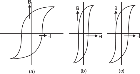
Fig. 5.25 Hysteresis loop for different magnetic materials (a) Hardsteel (b) Silicon steel (c) Wrought iron
- Hard steel: The hysteresis loop for hard steel is shown in Figure 5.25 (a). This loop has larger area that indicates that this material will have more hysteresis loss. Therefore, it is never used for the construction of machine parts. However, its loopshows that the material has high retentivity and coercivity. Therefore, it is more suitable for making permanent magnets.
- Silicon steel: The hysteresis loop for silicon steel is shown in Figure 5.25 (b). This loop has the smallest area that indicates that this material will have small hysteresis loss. Therefore, it is most suitable for the construction of those parts of electrical machines in which reversal of magnetisation is very quick, for example, armature of DC machines, transformer core, starter of induction motors, etc.
- Wrought iron: Figure 5.25 (c) shows the hysteresis loop for wrought iron. This loop shows that this material has fairly good residual magnetism and coercivity. Therefore, it is best suited for making cores of electromagnets.
Numericals
- Estimate the total mmf required to produce of a flux of 1 mWb round an iron ring of 6 cm2 cross section and 90 cm mean diameter having an air gap of 9 mm wide across it. The relative permeability of iron is 1.200.(Ans. 15,052 AT)(PU)
- A steel ring 15 cm mean radius and of circular section 1 cm in radius has an air gap of 1 mm length. It is wound uniformly with 500 turns of wire carrying a current of 3 A. Neglect magnetic leakage. The air gap takes 20% of the total mmf. Find reluctance.(Ans. 12.6 × 10⁶AT/Wb)
- An iron ring has cross section of 3 cm2 and a mean diameter of 25 cm. An air gap of 0.4 mm has been made by saw cut across the section. The ring is wound with 200 turns through which a current of 2 A is passed. If the total flux is 21 × 10−5 Wb, find µ for iron assuming no leakage.(Ans. 2,470) (PU)
- A circular iron ring has a mean circumference of 1.5 m and a cross-sectional area of 100 cm2. A saw cut of 0.4 cm wide is made in the ring. Calculate the magnetising current required to produce a flux of 0.8 mWb in the air gap if the ring is wound with a coil of 350 turns. Assuming relative permeability of iron as 400 and leakage factor as 1.25.(Ans. 1.58A)
- A steel ring 50 cm mean diameter and of circular section 3 cm in diameter has an air gap 2 mm long. It is wound uniformly with 1,000 turns of wire carrying a current of 4 A. Calculate mmf, magnetic flux, reluctance, and flux density. Neglect magnetic leakage. Iron path takes about 40% of total mmf.(Ans. 4,000 AT; 1.066 mWb; 3.753 ×10⁶ AT/Wb;1.508 T)
5.14 ELECTROMAGNETIC INDUCTION
The phenomenon by which an emf is induced in a circuit (and hence current flows when the circuit is closed) when magnetic flux linking with it changes is called electromagnetic induction.
For illustration, consider a coil having a large number of turns to which galvanometer is connected. When a permanent bar magnet is taken nearer to the coil or away from the coil, as shown in Figure. 5.26 (a), a deflection occurs in the needle of the galvanometer. Although, the deflection in the needle is opposite in two cases.
On the other hand, if the bar magnet is kept stationary and the coil is brought near to the magnet or away from the magnet, as shown in Figure 5.26 (b), again a deflection occurs in the needle of the galvanometer. The deflection in the needle is opposite in the two cases. However, if both the magnet and the coil are kept stationary, no matter how much flux is linking with the coil, there is no deflection in the galvanometer needle.
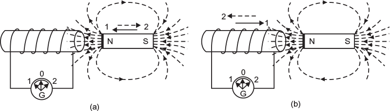
Fig. 5.26 Electromagnetic induction (a) Magnetic bar taken nearer to the coil or away from it (b) Coil taken nearer to the magnet or away from it
The following points are worth noting:
- The deflection in the galvanometer needle shows that emf is induced in the coil. This condition occurs only when flux linking with the circuit changes, that is, either magnet or coil is in motion.
- The direction of induced emf in the coil depends upon the direction of magnetic field and the direction of motion of coil.
Leave a Reply