A DC generator whose field winding is excited by the current supplied by the generator itself is called a self-excited DC generator. In a self-excited DC generator, the field coils may be connected in parallel with the armature, in series with the armature or partly in series, and partly in parallel with the armature winding. Accordingly, the self-excited generators may be classified as follows:
- Shunt-wound generators: In this generator, the field winding is connected across the armature winding forming a parallel or shunt circuit. Therefore, full terminal voltage is applied across the field winding. A very small current Ish flows through it, because this winding has many turns of fine wire having very high resistance Rsh (of the order of 100 Ω). Its conventional diagram is shown in Figure 11.17.
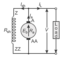 Fig. 11.17 Conventional diagram of a shunt wound DC generatorImportant relationsShunt field current, Ish = V/Rshwhere Rsh is the shunt field winding resistance. The field current Ish is practically constant at all loads, and therefore, the DC shunt machine is considered to be constant flux machine.Armature current, Ia = IL + Ish; terminal voltage, V = Eg − IaRaIncluding brush contact drop, V = Eg − Ia Ra − 2υbPower developed = Eg Ia; power output = VIL
 - Series-wound generators: In this generator, the field winding is connected in series with the armature winding forming a series circuit. Therefore, full line current IL or armature current Ia flows through it. Since the series field winding carries full-load current, it has a few turns of thick wire having low resistance (usually of the order of less than 1 Ω). Its conventional diagram is shown in Figure 11.18.
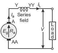 Fig. 11.18 Conventional diagram of a series wound DC generatorImportant relationsSeries field current, Ise = IL = IaSeries field winding resistance = RseTerminal voltage, V = Eg − Ia Ra − Ise Rse = Eg − Ia (Ra + Rse)Including brush contact drop, V = Eg − Ia (Ra + Rse) − 2vbPower developed = EgIa; power output = VIL = VIaNote: The flux developed by the series field winding is directly proportional to the current flowing through it (i.e., ɸ ∝ Ise). However, it is only true before magnetic saturation. After saturation, flux becomes constant even if the current flowing through it is increased.
 - Compound-wound generators: In a compound-wound generator, there are two sets of field windings on each pole. One of them is connected in series (having few turns of thick wire) and the other is connected in parallel (having many turns of fine wire) with armature. A compound-wound generator may be classified as follows:
- Long shunt: In this generator, the shunt field winding is connected in parallel with the combination of both armature and series field winding. The conventional diagram of lone shunt compound generator is shown in Figure 11.19.
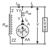 Fig. 11.19 Conventional diagram of a long shunt compound wound DC generatorImportant relationsShunt field current,
  Series field current, Ise = Ia = IL + IshTerminal voltage, V = Eg − Ia Ra − Ise Rse = Eg − Ia (Ra + Rse) Including brush contact drop, V = Eg − Ia (Ra + Rse) − 2vbPower developed = Eg Ia; power output = VIL
 - Short shunt: In this generator, the shunt field winding is connected in parallel with only armature winding. The conventional diagram of short-shunt compound generator is shown in Figure 11.20.
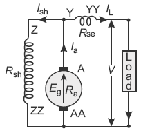 Fig. 11.20 Conventional diagram of a short shunt compound wound DC generatorImportant relationsSeries field current, Ise = ILShunt field current,
 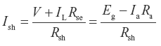 Ia = IL + IshTerminal voltage, V = Eg − IaRa − IL RseIncluding brush contact drop, V = Eg − Ia Ra − IL Rse − 2vbPower developed = Eg Ia; power output = VIL
- Long shunt: In this generator, the shunt field winding is connected in parallel with the combination of both armature and series field winding. The conventional diagram of lone shunt compound generator is shown in Figure 11.19.
Leave a Reply