We know that when a current carrying conductor is placed in the magnetic field, a force is exerted on it that exerts turning moment or torque (F × r) (see Fig. 11.38). This torque is produced due to electromagnetic effect, and hence it is called electromagnetic torque.
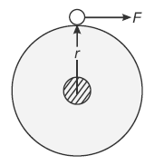
Fig. 11.38 Force exerted on a single conductor
ɸ = flux per pole in Wb
r = average radius of armature in metre
l = effective length of each conductor in metre
Z = total armature conductors
Ia = total armature current
A = number of parallel paths
Average force on each conductor, F = Bil Newton
Torque due to one conductor = F × r Newton metre
Total torque developed in the armature, T = ZFr Newton metre
or
T = ZBilr (11.1)
Now, current in each conductor, i = Ia/A
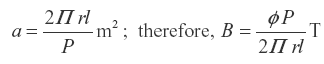
Average flux density, B = ɸ/a
where ‘a’ is the X-sectional area of flux path at radius r.
Obviously,
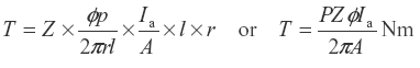
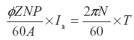
Substituting these values in Equation (11.1), we get
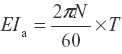
Alternately, the power developed in the armature is given as
EIa = ωT
or
or
or
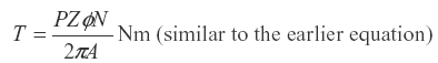
For a particular machine, the number of poles (P) and number of conductors per parallel path (Z/A) are constant.
Therefore,
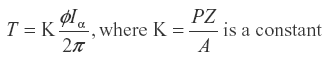
The constant K for a given machine is the same for the emf equation as well as for the torque equation.
Further, T = K2 ɸIa , where  is another constant. Thus, T ∝ ɸ Ia
Thus, we conclude that torque produced in the armature is directly proportional to flux per pole and armature current. Moreover, the direction of electromagnetic torque developed in the armature depends upon the direction of flux or magnetic field and the direction of flow of current in armature conductors. If either of the two is reversed, the direction of torque produced is reversed, and hence, the direction of rotation. However, when both are reversed, the direction of torque does not change.
Leave a Reply