The circuit containing a pure capacitor of capacitance C Farad is shown in Figure 7.5. Let the alternating voltage applied across the circuit be given as
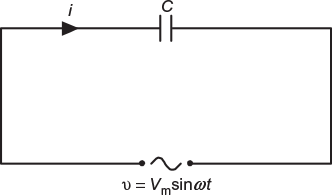
Fig. 7.5 Circuit diagram containing pure capacitor only
ν = Vm sin ω t (7.6)
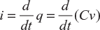
Charge on the capacitor at any instant,
q = Cv
Current flowing through the circuit,
or
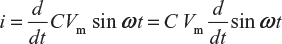
or

where XC = 1/ω C is the opposition offered to the flow of AC by a pure capacitor and is called capacitive reactance.
The value of current will be maximum when sin (ω t + π/2) = 1
i.e.,
Im = Vm/XC
Substituting this value is Equation (7.7), we get
i = Im sin (ω t + π/2) (7.8)
7.4.1 Phase Angle
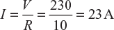
From Equations (7.6) and (7.8), it is clear that the current flowing through pure capacitive circuit leads the applied voltage by 90°. The phasor diagram and wave diagram are shown in Figure 7.6(a) and (b), respectively. Hence, in an AC circuit containing pure capacitance current leads the voltage by 90°.
Fig. 7.6 (a) Phasor diagram (b) Wave diagram for voltage, current and power
7.4.2 Power
Instantaneous power, p = vi = Vm sin ω t × Im sin (ω t + π/2)
= VmIm sin ωt cos ωt = ![]()
or average power over a complete cycle,
P = 0
Hence, average power consumed in a pure capacitive circuit is zero.
7.4.3 Power Curve
The power curve for a pure capacitive circuit is shown in Figure 7.6(b). It is very clear from the curve that average power in a half cycle (one alternation) is zero since the positive and negative loop area under power curve is the same.
It is interesting to note that during the first quarter cycle, whatever power (or energy) is supplied by the source to the capacitor is stored in the electric field set−up between the capacitor plates. In the next quarter cycle, the electric field collapses and the power (or energy) stored in the field is returned to the source. This process is repeated in each alternation. Hence, no power is consumed by this circuit.
Example 7.1
An AC circuit consists of a pure resistance of 10 Ω and is connected across an AC supply of 230 V, 50 Hz. Calculate (i) current, and (ii) power consumed; further, (iii) write down the equation for voltage and current.
Solution:
- Current in the circuit,
- Power consumed, P = VI = 230 × 23 = 5,290 W
- Maximum value of applied voltage, Vm =
 V = × 230 = 325.27VMaximum value of current, Im = × 23 = 32.53 AAngular velocity, ω = 2 π f = 2 π × 50 = 314.16 rad/sEquation for applied voltage;
ν = Vm sin ω t = 325.27 sin 314.16 t
As in a pure resistive circuit, voltage and current are in phase with each other, and therefore, current is given by the equation;
i = Im sin ω t = 32.53 sin 314.16 t
Example 7.2
An inductive coil having negligible resistance and 0.1 H inductance is connected across 200 V, 50 Hz supply. Find (i) the inductive reactance, (ii) rms value of current, (iii) power, and (iv) equations for voltage and current.
Inductive reactance,
XL = 2 π L = 2 π × 50 × 0.1 = 31.416 Ω
Current,
I = V/XL = 200/31.416 = 6.366 A
Power,
P = 0
Now,
Vm = ![]() V =
V = ![]() × 200 = 282.84 V;
× 200 = 282.84 V;
Im = ![]() I =
I = ![]() ×6.366 = 9A
×6.366 = 9A
and
ω = 2 π f = 314 rad/s
∴
ν = Vm sin ω t = 282.84 sin 314 t
In pure inductive circuit, current lags behind voltage by π/2 radian.
∴
i = Im sin (ω t − π/2) = 9 sin (314 t − π/2)
Example 7.3
A capacitor has a capacitance of 30 µF. Find its capacitive reactance for frequencies of 25 and 50 Hz. Find in each case the current if the supply voltage is 440 V.
Solution:
Capacitance of the capacitor, C = 30 × 10−6 F
Supply voltage, V = 440 V
When supply frequency, f1 = 25 Hz
Capacitive reactance,![]()
Current in the circuit, ![]()
When supply frequency f2 = 50 Hz,
capacitive reactance, ![]()
Current in the circuit, ![]()
Example 7.4
A 100 µF capacitor is connected across a 230 V, 50 Hz supply. Determine (i) the maximum instantaneous charge on the capacitor and (ii) the maximum instantaneous energy stored in the capacitor.
Solution:
- Maximum instantaneous charge on the capacitor = CVm = (100 × 10−6) × (230 × ) = 32.527 × 10⁻³ C
- Maximum instantaneous energy stored in the capacitor
Leave a Reply