An actual transformer has (i) primary and secondary resistances R1 and R2, (ii) primary and secondary leakage reactance X1 and X2 (iii) iron and copper losses and (iv) exciting resistance R0 and exciting reactance X0. The equivalent circuit of an actual transformer is shown in Figure 10.23.
Primary impedance, ![]() = R1 + jX1
= R1 + jX1
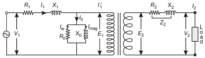
Fig. 10.23 Equivalent circuit of an actual transformer on load
Supply voltage is V1. The resistance and leakage reactance of primary winding are responsible for some voltage drop in primary winding.
∴
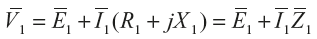
Where
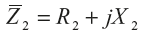
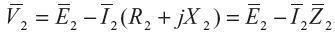
Secondary impedance,
Similarly, the resistance and leakage reactance of secondary winding are responsible for some voltage drop in secondary winding. Hence,
The phasor (vector) diagrams of an actual transformer for resistive, inductive, and capacitive loads are shown in Figure 10.24(a), 10.24(b), and 10.24(c), respectively. The drops in resistances are drawn in phase with current vectors and drops in reactance are drawn perpendicular to the current vectors.
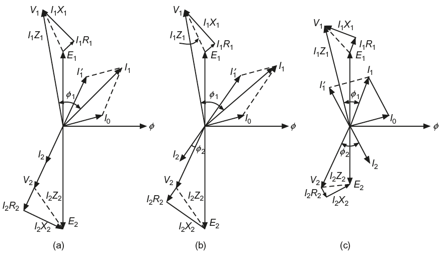
Fig. 10.24 Phasor diagram of an actual transformer at load (a) for resistive load (b) for inductive load (c) for capacitive load
Leave a Reply