Three slightly more complex functions are known as AND, OR, and XOR (Figure 10.15).
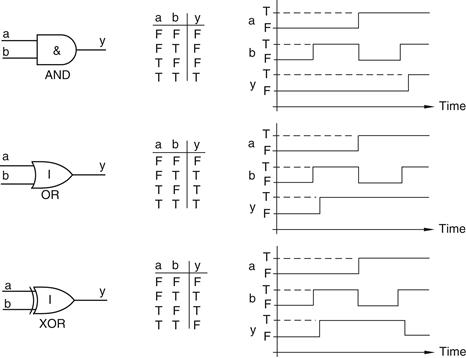
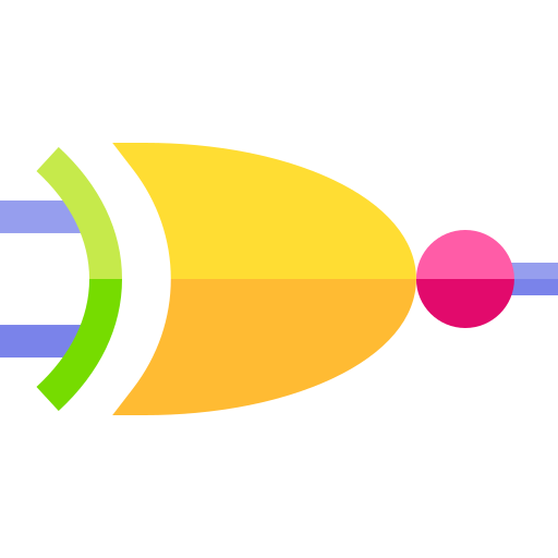
Figure 10.15 AND, OR, and XOR functions
The AND and OR representations shown here are the abstract equivalents of our original switch examples. In the case of the AND, the output is only TRUE if both a and b are TRUE; in the case of the OR, the output is TRUE if either a or b are TRUE. In fact, the OR should more properly be called an inclusive-OR, because the TRUE output cases include the case when both inputs are TRUE. Contrast this with the exclusive-OR, or XOR, where the TRUE output cases exclude the case when both inputs are TRUE.
10.10 NAND, NOR, and XNOR Functions
Now consider the effect of appending a NOT function to the output of the AND function (Figure 10.16).
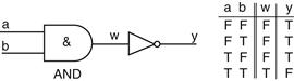
Figure 10.16 AND function followed by a NOT function
This combination of functions occurs frequently in designs. Similarly, the outputs of the OR and XOR functions are often inverted with NOT functions. This leads to three more primitive functions called NAND (NOT-AND), NOR (NOT-OR) and NXOR (NOT-XOR). However, in practice the NXOR is almost always referred to as an XNOR (exclusive-NOR) (Figure 10.17).
Figure 10.17 NAND, NOR, and XNOR functions
The bobbles on their outputs indicate that these are inverting functions. One way to visualize this is that the symbol for the NOT function has been forced back into the preceding symbol until only the bobble remains visible.
Of course, if we appended a NOT function to the output of a NAND, we’d end up back with our original AND function again. Similarly, appending a NOT to a NOR or an XNOR results in an OR and XOR, respectively.
10.11 Not a Lot
And that’s about it. In reality there are only eight simple functions (BUF, NOT, AND, NAND, OR, NOR, XOR, and XNOR) from which everything else is constructed. In fact, some might argue that there are only seven core functions because you can construct a BUF out of two NOTs, as was discussed earlier.
Actually, if you want to go down this path, you can construct all of the above functions using one or more NAND gates (or one or more NOR gates). For example, if you connect the two inputs of a NAND gate together, you end up with a NOT as shown in Figure 10.18 (you can achieve the same effect by connecting the two inputs of a NOR gate together).
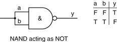
Figure 10.18 Forming a NOT from a NAND
As the inputs a and b are connected together, they have to carry identical values, so we end up showing only two rows in the truth table. We also know that if we invert the output from a NAND, we end up with an AND. So we could append a NAND configured as a NOT to the output of another NAND to generate an AND (Figure 10.19).
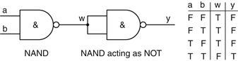
Figure 10.19 Forming an AND from two NANDs
Later on, we’ll discover how to transform functions formed from ANDs into equivalent functions formed from ORs and vice versa. Coupled with what we’ve just seen here, this would allow us to build anything we wanted out of a bunch of 2-input NAND (or NOR) functions.
10.12 Functions Versus Gates
Simple functions such as BUF, NOT, AND, NAND, OR, NOR, XOR, and XNOR are often known as primitive gates, primitives, logic gates, or simply gates. Strictly speaking, the term logic function implies an abstract mathematical relationship, while logic gate implies an underlying physical implementation. In practice, however, these terms are often used interchangeably.
More complex functions can be constructed by combining primitive gates in different ways. A complete design—say a computer—employs a great many gates connected together to achieve the required result. When the time arrives to translate the abstract representation into a particular physical implementation, the logic symbols are converted into appropriate equivalents such as switches, transistors, or pneumatic valves. Similarly, the FALSE and TRUE logic values are mapped into appropriate equivalents such as switch positions, voltage levels, or air pressures. The majority of designs are translated into a single technology. However, one of the advantages of abstract representations is that they allow designers to implement different portions of a single design in dissimilar technologies with relative ease. Throughout the remainder of this book we will be concentrating on electronic implementations.
Finally, if some of the above seems to be a little esoteric, consider a real-world example from your home, such as two light switches mounted at opposite ends of a hallway controlling the same light. If both of the switches are UP or DOWN the light will be ON; for any other combination the light will be OFF. Constructing a truth table reveals a classic example of an XNOR function.
10.12.1 Using Transistors to Build Primitive Logic Functions
There are several different families of transistors available to designers and, although the actual implementations vary, each can be used to construct primitive logic gates. This chapter concentrates on the metal-oxide semiconductor field-effect transistors (MOSFETs) introduced earlier, because their symbols, construction, and operation are easier to understand than are bipolar junction transistors (BJTs).
Logic gates can be created using only NMOS or only PMOS transistors; however, a popular implementation called complementary metal-oxide semiconductor (CMOS) makes use of both NMOS and PMOS transistors connected in a complementary manner.
CMOS gates operate from two voltage levels, which are usually given the labels VDD and VSS. To some extent the actual values of VDD and VSS are irrelevant as long as VDD is sufficiently more positive than VSS. There are also two conventions known as positive logic and negative logic.19 Under the positive logic convention used throughout this book, the more positive VDD is assigned the value of logic 1, and the more negative VSS is assigned the value of logic 0. Previously it was noted that truth table assignments can be specified using the abstract values FALSE and TRUE. However, electronic designers usually represent FALSE and TRUE as 0 and 1, respectively.
Leave a Reply