A transformer, in which a part of the winding is common to both primary and secondary circuits, is called an autotransformer. In a two-winding transformers, primary and secondary windings are electrically isolated, but in an autotransformer, the two windings are not electrically isolated rather a section of the same winding acts as secondary or primary of the transformer.
10.24.1 Construction
The core of an autotransformer may be rectangular (Figure 10.35(a)) or circular ring type (Figure 10.36(a)) in shape. A single winding is wound around one or two limbs of the rectangular core as shown in Figure 10.35(b) or it is wound over the ring as shown in Figure 10.36(b). Terminal ‘B’ is taken as a common point from which one terminal for primary and one terminal of the secondary is taken out. The second terminal of the secondary is connected to point ‘C’ which may be fixed or movable as shown in Figure 10.35(b) and 10.36(b). The number of turns between AB are taken as N1 and the number of turns between BC are taken as N2 as shown in Figure 10.35(c) and 10.36(c). Thus, one section of the same winding acts as a primary and the other section of the same winding acts as a secondary. When the number of secondary turns N2 is less than the primary turns N1 (i.e., N2 < N1) as shown in Figure 10.35(c) and 10.36(c), the autotransformer works as step-down transformer, whereas it works as a step-up transformer if number of secondary turns N2 is more than primary turns N1 as shown in Figure 10.35(d) and 10.36(d).
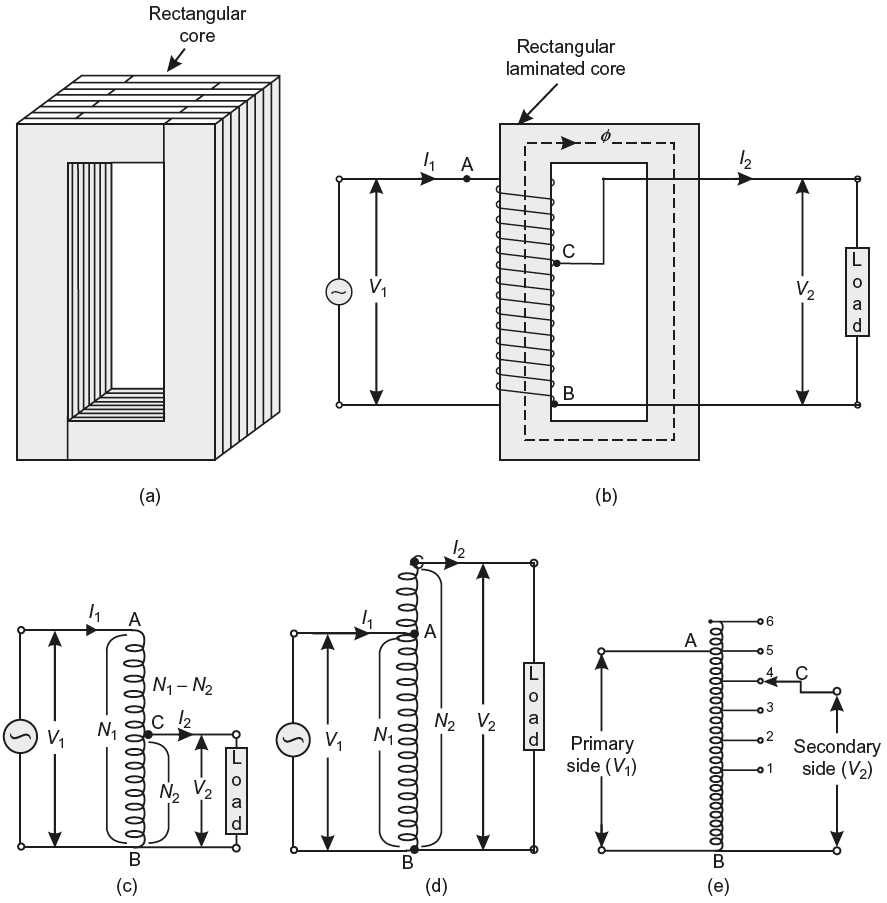
Fig. 10.35 (a) Rectangular core of an auto-transformer (b) Single winding placed on the core (c) Electric circuit for step-down auto-transformer (d) Electric circuit for step-up auto-transformer (e) Electric circuit of an auto-transformer
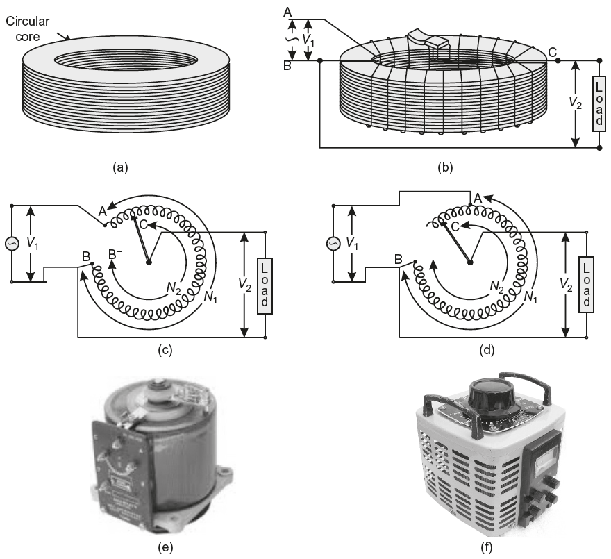
Fig. 10.36 (a) Circular core of an auto-transformer (b) Single winding placed on the core (c) electric circuit for step-down auto-transformer (d) Electric circuit for step-up auto-transformer (e) & (f) Pictorial view of an auto-transformer (or variac)
The pictorial view of a single-phase autotransformer used in laboratories is shown in Figure 10.36(e & f). Here, point C is attached to a movable arm which carries a carbon brush. The brush moves over number of turns wound over a circular laminated core and its position determines the output voltage.
10.24.2 Working
When AC voltage V1 is applied to winding AB, an exciting current starts flowing through the full winding AB if the internal impedance drop is neglected, then the voltage per turn in winding AB is V1/N1 and, therefore, the voltage across BC is (V1/N1)N2.
When switch S is closed, as shown in Fig. 10.37(a), a current I2 starts flowing through the load and current I1 is drawn from the source [see Fig. 10.37(b)]. Neglecting losses,
Input power = Output power
or
V1I1cos ɸ1 = V2I2cos ɸ2
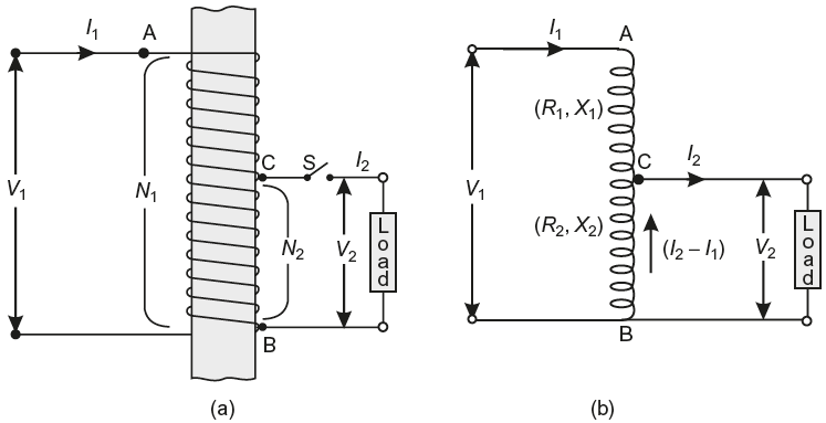
Fig. 10.37 (a) Winding of an auto-transformer placed around a limit of the core (b) Electric circuit of an auto-transformer
If internal (or leakage) impedance drops and losses are neglected, then
cos ɸ1 = cos ɸ2
Hence
V1I1 = V2I2
or
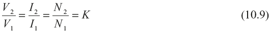
Here, K is less than unity. The expression is identical to a two-winding transformer.
Let at any instant, the exciting current flows from A to B and it establishes a working mmf directed vertically upward in the core. When switch S is closed, the current in winding BC must flow from B to C, in order to create an mmf opposing the exciting or working mmf, as per Lenz’s law. Since the working mmf in a transformer remains constant at its no-load value, the primary must draw additional current I1 from the source, in order to neutralise the effect of current IBC. In winding AB, I1 flows from A to B while in winding BC, I2 flows from B to C. Therefore, the current in winding BC is I1 from C to B and I2 from B to C. Here, the current I2 is greater than I1 (because V2 < V1) and their mmfs. are opposing each other at every instant, therefore,
IBC = I2 − I1
mmf of winding
AC = I1(N1− N2) = I1N1 − I1N2
= I2N2 − I1N2 = (I2 − I1) N2 [∴ I1N1 = I2N2]
= mmf of winding CB.
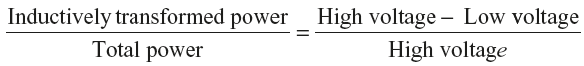
It is, therefore, seen that the transformer action takes place between winding, section AC and winding section BC. In other words, the volt-amperes across winding AC are transferred by transformer action to the load connected across winding BC.
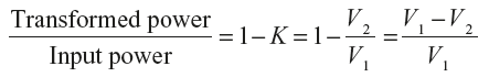
∴ Power transformed in VA = VACIAC = (V1 − V2) I1
Total power to be transferred or input power in VA = V1I1
∴
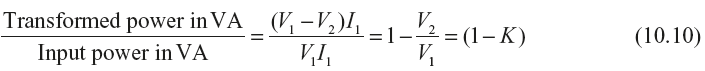
Power transformed = (1 − K) × power input
Out of the input volt-amperes V1I1, only VACIAC = (V1 − V2) I1 is transformed to the output by transformer action. The remaining power in volt-ampere required for the output, are conducted directly to the secondary from the primary (due to electrical connection).
∴ Power conducted in VA = Total power input in VA − transformed power in VA
= V1I1 − (V1 − V2) I1 = V2I1
∴
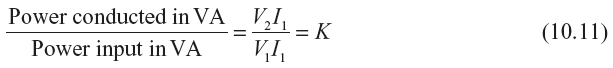
Power conducted = K × power input
Hence,
And
Considering eqn. (10.12),
or
10.25 AUTOTRANSFORMER V/S POTENTIAL DIVIDER
At first sight, an autotransformer appears to be similar to a resistance potential divider. But this is not so, as described below.
- A resistive potential divider cannot step up the voltage, whereas it is possible in an autotransformer.
- The potential divider has more losses and is, therefore, less efficient.
- In a potential divider, almost entire power to load flows by conduction, whereas in auto-transformer, a part of the power is conducted and the rest is transferred to load by transformer action.
- In a potential divider, the input current, must always be more than the output current, this is not so in an autotransformer. If the output voltage in autotransformer is less than the input voltage, the load current is more than the input current.
Leave a Reply