
The simplest of all the logic functions are known as BUF and NOT (Figure 10.13).
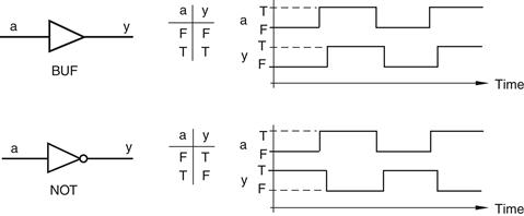
Figure 10.13 BUF and NOT functions
The F and T values in the truth tables are shorthand for FALSE and TRUE, respectively. The output of the BUF function has the same value as the input to the function; if the input is FALSE the output is FALSE, and if the input is TRUE the output is TRUE. By comparison, the small circle, or bobble, on the output of the NOT symbol indicates an inverting function; if the input is FALSE the output is TRUE, and if the input is TRUE the output is FALSE.
As a reminder that these abstract functions will eventually have physical realizations, the waveforms show delays between transitions on the inputs and corresponding responses at the outputs. The actual values of these delays depend on the technology used to implement the functions, but it is important to note that in any physical implementation there will always be some element of delay.
Now consider the effect of connecting two NOT functions in series (one after the other) as shown in Figure 10.14.
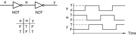
Figure 10.14 Two NOT functions connected together in series
The first NOT gate inverts the value from the input, and the second NOT gate inverts it back again. Thus, the two negations cancel each other out (sort of like “two wrongs do make a right”). The end result is equivalent to that of a BUF function, except that each NOT contributes an element of delay.
Leave a Reply