Single-phase small rating transformers are shown in Figure 10.4. According to the core construction and the manner in which the primary and secondary are placed around it, the transformers are named as follows:
- Core-type transformers
- Shell-type transformers
- Berry-type transformers
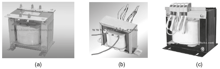
Fig. 10.4 (a), (b) and (c) Small rating 1-phase transformers
10.4.1 Core-type Transformers
In a simple core-type transformer, the magnetic core is built up of laminations to form a rectangular frame. The laminations are cut in the form of L-shape strips as shown in Figure 10.5. In order to avoid high reluctance at the joints where laminations are butted against each other, the alternate layers are stacked differently to eliminate continuous joint as shown Figure 10.6(a).
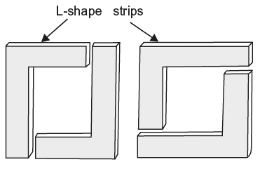
Fig. 10.5 L-shaped laminations
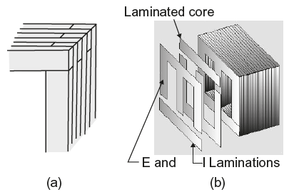
Fig. 10.6 (a) Alternate layer of joints (b) E & I laminations
The upper horizontal portion of the core is known as a yoke and the vertical portion as a limb, as shown in Figure 10.7(b). This carries the windings. Usually, the cross-sectional area of yoke is kept 15 to 20 per cent more than the limbs because it reduces the flux density and consequently reduces the iron losses.
In actual transformer construction, the primary and secondary windings are interleaved to reduce the leakage flux. Half of each winding is placed side by side or concentrically on either limb or leg of the core as shown in Figure 10.7. However, for simplicity, the two windings are shown in Figure 10.3(a) located on separate limbs of the core.
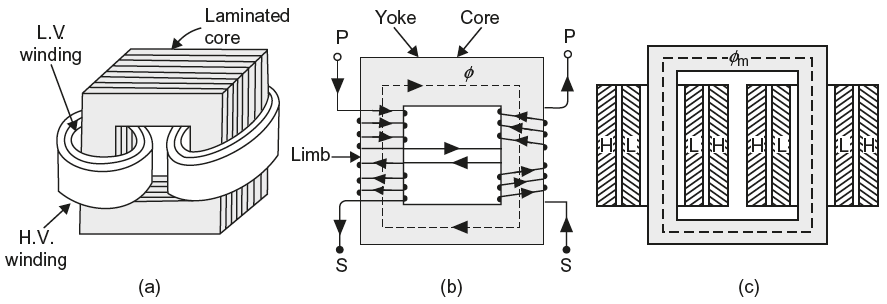
Fig. 10.7 (a), (b) and (c) Method to place LV and HV winding in core-type transformer
While placing these windings, an insulation layer (Bakelite former) is provided between core and lower winding and between the two windings. To reduce the insulation, low-voltage winding is always placed nearer the core as shown in Figure 10.7(a). The windings used are form wound (usually cylindrical in shape) and the laminations are inserted later on.
10.4.2 Shell-type Transformers
In case of shell-type transformer, each lamination is cut in the form of long strips of E’s and I’s as shown in Figure 10.8. In order to avoid high reluctance at the joints where the laminations are butted against each other, the alternate layers are stacked differently to eliminate continuous joints.
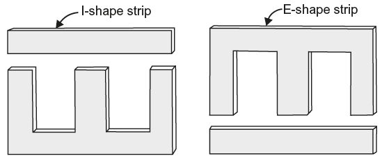
Fig. 10.8 E and I laminations for shall type core construction
In a shell-type transformer, the core has three limbs. The central limb carries whole of the flux, whereas the side limbs carry half of the flux. Therefore, the width of the central limb is about double to that of the outer limbs.
Both the primary and secondary windings are placed on the central limb side by side or concentrically (Fig 10.9). The low-voltage winding is placed nearer the core and high-voltage winding is placed outside the low-voltage winding to reduce the cost of insulation placed between core and low-voltage winding. In this case, the windings are form wound is cylindrical shape and the core laminations are inserted later on.
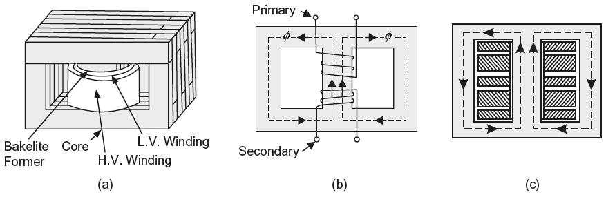
Fig. 10.9 (a), (b) and (c) Method to place LV and HV winding in shall-type transformer
The whole assembly, that is, core and winding is then usually placed in tank filled with transformer oil. The transformer oil provides better cooling to the transformer and acts as a dielectric medium between winding and outer tank which further reduces the size of outer tank of the transformer.
The comparison between core type and shall type transformers is given in Table 10.1
Table 10.1 Comparison between Core-type and Shell Type Transformers
| S.No. | Core-type Transformer | Shell-type Transformer |
|---|---|---|
| 1. | The windings surround a considerable portion of the core. | The core surrounds considerable portion of the windings. |
| 2. | Windings are of form-wound and are of cylindrical-type. | Windings are of sandwich type. The coils are first in the form of pancakes, and complete winding consists of stacked discs. |
| 3. | More suitable for high-voltage transformers. | More suitable and economical for low-voltage transformers. |
| 4. | Mean length of coil turns is shorter. | Mean length of coil turn is longer. |
| 5. | Core has two limbs to carry the windings. | Core has three or more limbs but the central limb carries the windings. |
10.4.3 Berry-type Transformers
A commonly used shell-type transformer is the one known as Berry-transformer so-called after the name of its designer and is cylindrical in shape. The transformer core consists of laminations arranged in groups which radiate from the centre as shown (as top view) in Figure 10.10.
It may be pointed out that cores and coils of transformers must be provided with rigid mechanical bracing in order to prevent movement and possible insulation damage. Good bracing reduces vibration and the objectionable noise–a humming sound–during operation.
Leave a Reply