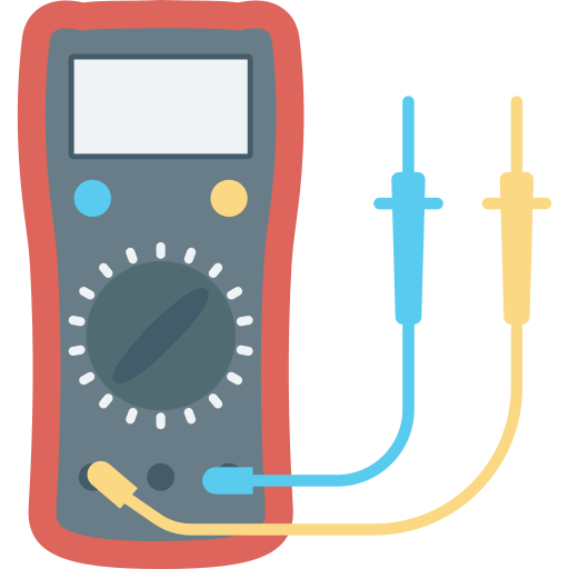
A digital multimeter (DMM) displays the AC or DC voltages being measured directly as discrete numerals in the decimal number system. Numerical readout of DMM is very convenient and it eliminates observational error. The use of digital multimeters increases the speed with which the readings can be taken.
The DMM is a versatile and accurate instrument used in laboratories. On account of developments in the integrated circuits (IC) technology, it has become possible to reduce the size, power requirements, and cost of digital multimeters.
The basic function performed by a digital multimeter is an analogue to digital (A/D) conversion. For example, the voltage value may be changed to a proportional time interval, which starts and stops a clock oscillator. In turn, the oscillator output is applied to an electronic counter that is provided with a readout in terms of voltage. There are many ways of converting the analogue reading into digital form, but the most common way is to use ramp voltage. The operating principle of a ramp-type DMM is simple. A ramp voltage increases linearly from zero to a predetermined level in a predetermined time interval. The ramp voltage value is continuously compared with the voltage being measured. At the instant, the value of ramp voltage becomes equal to that of unknown voltage, a coincidence circuit called input comparator, generates a pulse that opens the gate as shown in Figure 9.42. The ramp voltage continues to decrease till it reaches the ground level. At this instance, another comparator generates a pulse and closes the gate. The time interval between the opening and the closing of gate is measured with an electronic time-interval counter. This count is displayed as a number of digits.
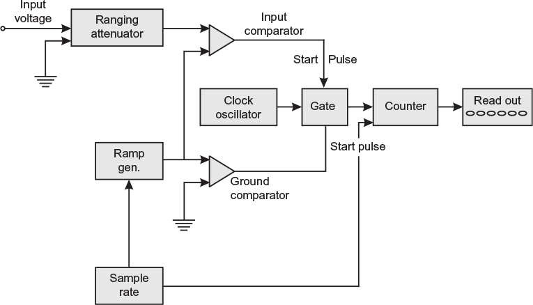
Fig. 9.42 Block diagram of a digital multimeter
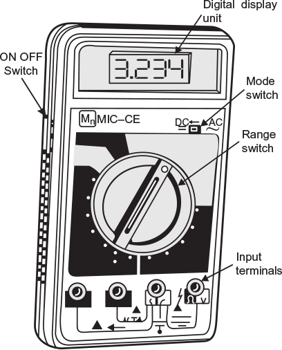
Fig. 9.43 Outer view of a digital multimeter
Figure 9.43 shows the pictorial view of a DMM. The main parts on the panel are as follows:
- Digital display unit: It displays the reading in digits.
- ON–OFF switch: It is used to switch ON and OFF the power of battery.
- Input terminals: There are four sockets; one of them is common to which black lead is inserted. The other three sockets to which red lead is connected are: (a) V – for measurement of DC and AC voltage and resistance; (b) A – for measurement of DC and AC current up to 2 A; and (c) 10A – for measurement of DC and AC current up to 10 A.
- Mode switch: For measurement of either DC or AC voltage or current, this switch is used to select the mode.
- Range switch: The central switch is used to select the range of quantity (voltage, current, or resistance) to be measured.
Leave a Reply