The simplified phasor diagram of R–L series circuit is shown in Figure 7.10. When each side of this phasor diagram is divided by a common factor I, we get another right−angled triangle, as shown in Figure 7.11, whose sides represent R, XL, and Z. Such a triangle is known as impedance triangle.
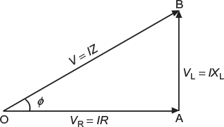
Fig. 7.10 Phasor diagram for R−L series circuit
Therefore, a right−angled triangle whose base represents circuit resistance, perpendicular represents circuit reactance, and hypotenuse represents circuit impedance is called an impedance triangle. The concept of impedance triangle is useful since it enables us to calculate:
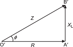
Fig. 7.11 Impedance triangle
Leave a Reply