
On February 9, 1907, one of Marconi’s engineers, Mr. H.J. Round of New York, NY, had a letter published in “Electrical World” magazine as follows:
A Note on Carborundum
To the editors of Electrical World:
Sirs: During an investigation of the unsymmetrical passage of current through a contact of carborundum and other substances a curious phenomenon was noted. On applying a potential of 10 volts between two points on a crystal of carborundum, the crystal gave out a yellowish light.
Mr. Round went on to note that some crystals gave out green, orange, or blue light. This is quite possibly the first documented reference to the effect upon which special components called light-emitting diodes (LEDs) are based.
Sad to relate, no one seemed particularly interested in Mr. Round’s discovery, and nothing really happened until 1922, when the same phenomenon was observed by O.V. Losov in Leningrad. Losov took out four patents between 1927 and 1942, but he was killed during the Second World War and the details of his work were never discovered.
In fact, it wasn’t until 1951, following the discovery of the bipolar transistor, that researchers really started to investigate this effect in earnest. They found that by creating a semiconductor diode from a compound semiconductor formed from two or more elements—such as gallium arsenide (GaAs)—light is emitted from the PN junction, that is, the junction between the P-type and N-type doped materials.
As for a standard diode, a LED conducts electricity in only one direction (and it emits light only when it’s conducting). Thus, the symbol for an LED is similar to that for a normal diode, but with two arrows to indicate light being emitted (Figure 10.10).

Figure 10.10 Symbol for a LED
A LED formed from pure gallium arsenide emits infrared light, which is useful for sensors, but which is invisible to the human eye. It was discovered that adding aluminum to the semiconductor to give aluminum gallium arsenide (AlGaAs) resulted in red light humans could see. Thus, after much experimentation and refinement, the first red LEDs started to hit the streets in the late 1960s.
LEDs are interesting for a number of reasons, not the least of which is that they are extremely reliable, they have a very long life (typically 100,000 hours as compared to 1,000 hours for an incandescent light bulb), they generate very pure, saturated colors, and they are extremely energy efficient (LEDs use up to 90% less energy than an equivalent incandescent bulb).
Over time, more materials were discovered that could generate different colors. For example, gallium phosphide gives green light, and aluminum indium gallium phosphite can be used to generate yellow and orange light. For a long time, the only color missing was blue. This was important because blue light has the shortest wavelength of visible light, and engineers realized that if they could build a blue laser diode, they could quadruple the amount of data that could be stored on, and read from, a CD-ROM or DVD.
However, although semiconductor companies spent hundreds of millions of dollars desperately trying to create a blue LED, the little rapscallion remained elusive for more than three decades. In fact, it wasn’t until 1996 that the Japanese electrical engineer Shuji Nakamura demonstrated a blue LED based on gallium nitride. Quite apart from its data storage applications, this discovery also makes it possible to combine the output from a blue LED with its red and green cousins to generate white light. Many observers believe that this may ultimately relegate the incandescent light bulb to the museum shelf.
10.7.1 Primitive Logic Functions
Consider an electrical circuit consisting of a power supply, a light, and two switches connected in series (one after the other). The switches are the inputs to the circuit and the light is the output. A truth table provides a convenient way to represent the operation of the circuit (Figure 10.11).
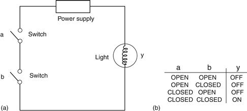
Figure 10.11 Switch representation of a 2-input AND function (a) Circuit; (b) Truth table
As the light is only ON when both the a and b switches are CLOSED (ON), this circuit could be said to perform a 2-input AND function. In fact, the results depend on the way in which the switches are connected; consider another circuit in which two switches are connected in parallel (side by side) (Figure 10.12).
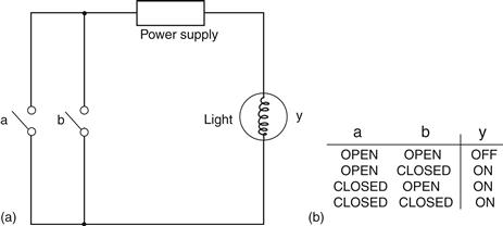
Figure 10.12 Switch representation of a 2-input OR function (a) Circuit; (b) Truth table
In this case, as the light is ON when either a or b are CLOSED (ON), this circuit could be said to provide a 2-input OR function.11 In a limited respect, we might consider that these circuits are making simple logical decisions; two switches offer four combinations of OPEN (OFF) and CLOSED (ON), but only certain combinations cause the light to be turned ON.
Logic functions such as AND and OR are generic concepts that can be implemented in a variety of ways, including switches as illustrated above, transistors for use in computers, and even pneumatic devices for use in hostile environments such as steel works or nuclear reactors. Thus, instead of drawing circuits using light switches, it is preferable to make use of more abstract forms of representation. This permits designers to specify the function of systems with minimal consideration as to their final physical realization. To facilitate this, special symbols are employed to represent logic functions, and truth table assignments are specified using the abstract terms FALSE and TRUE. This is because assignments such as OPEN, CLOSED, ON, and OFF may imply a particular implementation.
Leave a Reply