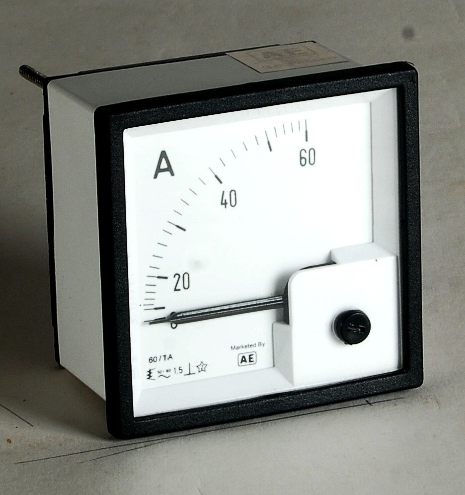
These instruments are quite cheap in cost, simple in construction, and reasonably accurate at fixed power supply frequency. These instruments can be used both on AC and DC. Therefore, these are widely used in laboratories and on switching panels. These instruments are used either as voltmeter or ammeter only. The pictorial view of these instruments is shown in Figures 9.11 and 9.12, respectively.
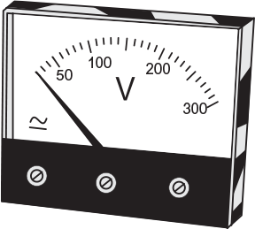
Fig. 9.11 Voltmeter
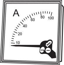
Fig. 9.12 Ammeter
Moving iron instruments are of two types, namely attraction type and repulsion type.
9.8.1 Attraction-type Moving Iron Instruments
Principle
The basic principle of an attraction-type moving iron instrument is illustrated in Figure 9.13. When a soft iron piece (or vane) is placed in the magnetic field of a current-carrying coil, it is attracted towards the centre of the coil. This is because the piece tries to occupy a position of minimum reluctance. Thus, a force of attraction is exerted on the soft iron piece and deflection in the needle takes place. Hence, the name attraction-type moving iron instrument.
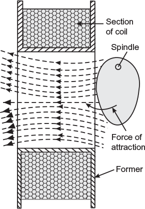
Fig. 9.13 Attraction type moving-iron instruments
Construction
The sectional view of an attraction-type moving iron instrument is shown in Figures 9.14 and 9.15. It consists of a stationary hollow cylindrical coil. An oval-shaped soft iron piece is mounted eccentrically to the spindle to which a pointer (needle) is attached. The controlling torque is provided by spring control method while damping torque is provided by air friction, as shown in Figures 9.14 and 9.15.
Working
When the instrument is connected in the circuit, an operating current (i.e., current to be measured in ammeter and current proportional to voltage to be measured in voltmeter) flows through the stationary coil. A magnetic field is set up and the soft iron piece is magnetised that is attracted towards the centre of the coil, as shown in Figure 9.13. Thus, the pointer attached to the spindle is deflected over the calibrated scale.
If current in the coil is reversed, the direction of magnetic field produced by the coil will reverse. In turn, this will also reverse the magnetism produced in the soft iron piece. Hence, the direction of deflecting torque remains unchanged. Thus, these instruments can be used on DC as well as on AC system.
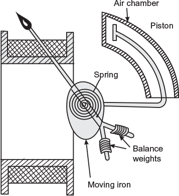
Fig. 9.14 Sectional view of attraction type moving iron instrument
Deflecting torque
The deflecting torque Td depends upon the force acting on the soft iron piece. Let
H = field strength produced by the coil;
m = pole strength of the soft iron piece, and (m ∝ H)
Pulling force acting on the movable iron piece,
F ∝ m × H or F ∝ H2
Now, H ∝ I
∴
F ∝ I2
As deflecting torque, Td ∝ F
∴
Td ∝ I2
The controlling torque Tc is provided by the spiral spring
∴
Tc ∝ θ (where θ is angle of deflection)
In steady position of deflection, Tc = Td
∴
θ ∞ I2 (I is the rms value of current in AC)
Since deflection θ ∝ I2, the scale of such an instrument is non-uniform, being crowded in the beginning. However, by choosing proper dimensions, shape and position of soft iron piece (vane), it is possible to design and construct an instrument with a scale that is very nearly uniform over a considerable part of its length.
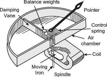
Fig. 9.15 Attraction type moving iron instrument with air friction damping
9.8.2 Repulsion-type Moving Iron Instruments
Principle
The basic principle of a repulsion-type moving iron instrument is that the repulsive forces will act between two similarly magnetised iron pieces when placed near to each other.
The sectional view of such an instrument is shown in Figure 9.16. It consists of a fixed cylindrical hollow coil that carries the operating current. Inside the coil, there are two soft iron pieces (rods or vanes) placed parallel to each other and along the axis of the coil. One of the rod or vane is fixed and the other is movable connected to the spindle. A pointer is attached to the spindle that gives deflection on the scale. The controlling torque is provided by spring control method, while damping torque is provided by air friction, as shown in Figure 9.16.
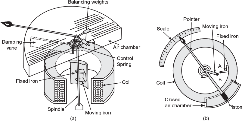
Fig. 9.16 Sectional view of repulsion type moving iron instrument (b) Top view of repulsion type moving iron instrument
Working
When the instrument is connected in the circuit, the operating current flows through the coil. A magnetic field is set up along the axis of the coil. This field magnetises both the iron pieces, and therefore, both the pieces attain similar polarities. A force of repulsion acts between the two; therefore, movable piece moves away from the fixed piece. Thus, the pointer attached to the spindle deflects over the calibrated scale.
If current in the coil is reversed, the direction of magnetic field produced by the coil is reversed. Although the polarity of the magnetised soft iron pieces is reversed but still they are magnetised similarly and repel each other. Hence, the direction of deflecting torque remains unchanged. Thus, these instruments can be used on DC as well as on AC system.
Deflecting torque
The deflecting torque depends upon the repulsive force acting between the similarly magnetised iron pieces. Let,
H = field strength produced by the coil;
m1 = pole strength of the fixed iron piece; (m1 ∝ H)
m2 = pole strength of the movable iron piece; (m2 ∝ H)
∴ Repulsive force acting on the movable iron piece,
F ∝ m1m2 or F ∝ H2;
Now,
H ∝ I
∴
F ∝ I2
As deflecting torque, Td ∝ F
∴
Td ∝ I2
The controlling torque Tc is provided by the spring
∴
Tc ∝ θ (where θ is angle of deflection)
At steady position of deflection, Tc ∝ Td
∴
θ ∝ I2 (I is the rms value of current in AC)
Since deflection θ ∝ I2, and therefore, the scale of such an instrument is non-uniform, being crowded in the beginning. However, by using tongue-shaped iron pieces, scale of such instruments can be made almost uniform.
9.8.3 Advantages and Disadvantages of Moving Iron Instruments
Advantages
- They are cheap in cost, mechanically robust, and simple in construction.
- They can be used on both AC and DC.
- They are reasonably accurate.
- They possess high operating torque.
- They can withstand overloads momentarily.
Disadvantages
- They cannot be calibrated with a high degree of precision with DC on account of the effect of hysteresis in the iron rods or vanes.
- They have non-uniform scale crowded at the beginning, and therefore, it is difficult to get accurate readings at this end.
- They are not very sensitive.
- Power consumption is quite high.
- Errors are introduced due to change in frequency in the case of AC measurements.
9.8.4 Errors in Moving Iron Instruments
There are two types of errors that occur in moving iron instruments:
Errors with both DC and AC
The following errors may occur in moving iron instruments when these are used either on DC or AC.
- Error due to hysteresis: Because of hysteresis in the iron parts of operating system, the readings are higher for descending value but lower for ascending values. The errors due to hysteresis are considerably reduced by using Mumetal or Permalloy that have negligible hysteresis loss.
- Error due to stray magnetic fields: Since the operating magnetic field of these instruments is comparatively weak, and therefore, stray fields (fields other than the operating magnetic field) affect these instruments considerably. Thus, the stray fields cause serious errors. These errors can be minimised by using an iron case or a thin iron shield over the working parts.
- Error due to temperature: In moving iron instruments, the change in temperature affects mainly the temperature coefficient of spring. With the change in temperature, stiffness of the spring varies that causes errors. However, for voltmeters both the temperature co-efficient of spring and temperature co-efficient of resistance of voltmeter circuit may balance each other.
However, in the case of shunt connected instruments, it is observed that the uncompensated instruments tend to read low by approximately 0.2%/ºC rise in temperature. Temperature compensation may be affected by connecting a resistor called the swamping resistor in series with the moving coil. The swamp resistor is made of Manganin combined with copper in the ratio of 20:1 to 30:1, which is hardly affected by temperature variations. The total resistance of the moving coil and swamping resistor increases slightly with a rise in temperature, but only just enough to overcome the effect of springs and magnets, so that the overall temperature effect is zero.
Errors with AC only
Error due to change in frequency
The change in frequency produces change in impedance of the coil and change in magnitude of eddy currents. The increase in impedance of the coil with the increase in frequency causes serious errors in the case of voltmeters only. However, this error can be eliminated by connecting a condenser of suitable value in parallel with the swamp resistance ‘r’ of the instrument. The impedance of the whole circuit of the instrument becomes independent of frequency if C = L/r2, where C is the capacitance of the condenser.
Ranges
- Ammeters: From about 0-20 mA to 0-800, maximum without current transformer.
- Voltmeters: From about 0-1V to 0-800 V, maximum without potential transformer.
9.8.5 Applications of Moving Iron Instruments
The moving iron instruments are used as ammeters and voltmeters only. These instruments can work on both AC and DC system.
Ammeter
An instrument that is used to measure electric current in an electric circuit is called an ammeter. An ammeter is connected in series with the circuit or load whose current is to be measured (Fig. 9.17). The operating coil of the instrument is to carry the whole of the current to be measured or fraction of it. When current flows through the operating coil, the desired deflecting torque is produced. Since an ammeter is connected in series, it should have low resistance to keep the circuit conditions to be the same. Hence, the operating coil of an ammeter should have a few turns of thick wire.
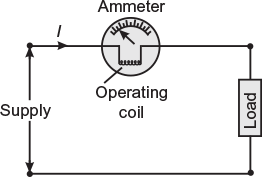
Fig. 9.17 Ammeter connected in series
Voltmeter
An instrument that is used to measure potential difference (or voltage) across the load or between two points in a circuit is called a voltmeter. A voltmeter is always connected in parallel with the load or portion of the circuit whose voltage is to be measured (Fig. 9.18). The deflection of the meter depends upon the current (Iv) flowing through the operating coil that is proportional to the voltage across the meter (Iv ∞ V). Since a voltmeter is connected in parallel, it should have high resistance to keep the circuit2 conditions to be the same. Hence, the operating coil of a voltmeter should have a large number of turns of thin wire. However, it is not sufficient, and therefore, a high resistance is connected in series with the operating coil (Fig. 9.18).
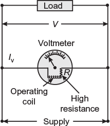
Fig. 9.18 Voltmeter connected in parallel
Example 9.2
A moving iron instrument gives full-scale deflection with 100 V. It has a coil of 20,000 turns and a resistance of 2,000 Ω. If the instrument is to be used as an ammeter to give full-scale deflection at 2 A, calculate the necessary number of turns in the coil.
Solution:
Full-scale deflection current, ![]()
In moving iron instruments, the strength of magnetic field (and hence, deflecting torque) depends upon AT of the operating coil.
∴ Full-scale deflection AT = NI = 20,000 × 0.05 = 1,000 AT
∴ Turns required to measure ![]()
Learning outcome: The magnitude of deflecting torque depends upon the magnetic strength provided by the operating coil that further depends upon AT (NI) of the coil (the larger the amount, the smaller is the number of turns for required flux).
Example 9.3
The coil of a 250 V moving iron voltmeter has a resistance of 500 Ω and an inductance of 1 H. The current taken by the instrument when placed on 250 V, DC supply is 0.05 A. Determine the percentage error when the instrument is placed on 250 V, 100 Hz AC supply.
Resistance of voltmeter coil, R = 500 Ω
Inductance of voltmeter coil, L = 1 H
Current taken by the instrument when placed on 250 V DC
Idc = 0.05 A
Total ohmic resistance ![]()
∴ Series swamp resistance, r = 5,000 − 500 = 4,500 Ω
When the instrument is placed on 250 V, 100 Hz AC
Inductive reactance of the coil, XL = 2πfL = 2π × 100 × 1 = 628.32 Ω
Impedance of the coil, 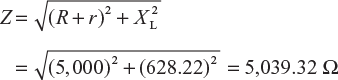
Current flowing through the coil, ![]()
Deflection or voltmeter reading with this current ![]()
Percentage error ![]()
Learning outcome: If moving iron instruments are calibrated on DC, they will not read accurately on AC if some compensation is not provided. Hence, an error crops in.
Example 9.4
An AC voltmeter with a maximum scale reading of 50 V has an inductance of 0.09 H and a total resistance of 500 Ω. The coil is wound with copper wire having a resistance of 50 Ω and the remainder of the voltmeter circuit consists of nine non-inductive resistances in series with the coil. Find the capacitance that should be placed across the non-inductive resistor to make the instrument read correctly both on DC as well as on AC.
Solution:
Total resistance, RE = 500 Ω; coil resistance, RC = 50 Ω
swamp resistance, r = RE – RC = 500 – 50 = 450 Ω; inductance, L = 0.09 H
Capacitance required to be connected in parallel with the swamp resistance to make the instrument independent of frequency.
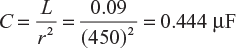
Learning outcome: The frequency error in moving iron instruments can be eliminated by providing a suitable capacitor in parallel with the swamp resistance.
Leave a Reply