
When load is applied on the induction motor, its speed decreases slightly and slip increases. Therefore, rotor current I2 increases. Simultaneously, to meet with this load, motor draws extra current from the supply mains similar to that of a transformer. In fact, power is transferred through magnetic field or flux.
The complete circuit diagram and phasor diagram of a loaded induction motor is shown in Figure 12.17(a) and (b), respectively.
Here, X0 – exciting reactance 
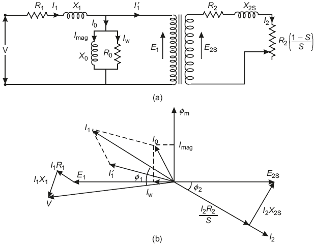
Fig. 12.17 (a) Equivalent circuit of an induction motor (b) Phasor diagram of an induction motor
R0 – exciting resistance ![]()
All other abbreviations have their usual meaning.
12.17.1 Causes of Low-power Factor
The basic principle of operation of an induction motor is mutual induction. When three-phase supply is given to a three-phase wound stator of an induction motor, a revolving field is set up in the stator. This field (flux) is also set up in the air between stator and rotor, which links with rotor conductors and emf is induced in them by mutual induction.
To set up the mutual flux, induction motor draws magnetizing current (Imag) from the mains which lags behind the voltage by 90° as shown in Figure 12.16(b) and 12.17(b). The magnitude of this current is quite large because of high reluctance of the air gap between stator and rotor.
The power factor of the induction motor is minimum at no-load as shown in Figure 12.16(b) since the magnetizing current has its dominating effect. However, the power factor increases with increase in load on the induction motor and is maximum at full-load as shown in Figure 12.17(b). Therefore, it is advised to operate the induction at full-load.
Therefore, because of air gap, induction motor draws large magnetizing current and operates at low lagging power factor.
Leave a Reply