Consider a phasor ![]() lying along OX-axis as shown in Figure 7.61. The phasor is reversed when it is multiplied by −1, that is, the phasor is rotated through 180° in counter clockwise (CCW) direction and attains the position along OX′-axis. Let us consider j as a factor which when multiplied by the phasor
lying along OX-axis as shown in Figure 7.61. The phasor is reversed when it is multiplied by −1, that is, the phasor is rotated through 180° in counter clockwise (CCW) direction and attains the position along OX′-axis. Let us consider j as a factor which when multiplied by the phasor ![]() , the phasor is rotated through 90° in CCW direction. This means that multiplying the phasor by j2 is the same as multiplying by −1. Therefore, it follows that
, the phasor is rotated through 90° in CCW direction. This means that multiplying the phasor by j2 is the same as multiplying by −1. Therefore, it follows that
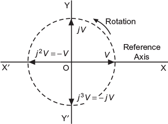
Fig. 7.61 Vector representation by j-notation
j2 = −1 or 1j = ![]()
Therefore, it is concluded that j is just an operator that is when multiplied with a phasor, it shows that the phasor is rotated through 90° in CCW direction. Each successive multiplication of j, rotates the phasor further by 90° as
j = ![]() ………………..90° CCW rotation from OX-axis
………………..90° CCW rotation from OX-axis
j2 = −1………………….180° CCW rotation from OX-axis
j3 = j2j = −![]() ………..270° CCW rotation from OX-axis
………..270° CCW rotation from OX-axis
j4 = j2j2 = 1…………….360° CCW rotation from OX-axis
The symbol j is used to represent the vertical (quadrature) components of phasor quantities. For instance, consider a phasor V rotated through θ° counter clockwise from OX-axis as shown in Figure 7.62(a). The phasor has two rectangular components (i) the horizontal component ‘a‘ along X-axis and (ii) the vertical component ‘b‘ rotated through 90° in CCW direction from OX-axis and is expressed as ‘jb‘. Therefore, in rectangular form, the phasor ![]() is represented as:
is represented as:
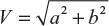
![]() = a + jb having magnitude
= a + jb having magnitude ![]() and angle θ = tan−1 (b/a) [positive]
and angle θ = tan−1 (b/a) [positive]
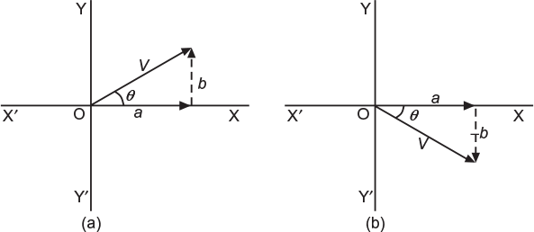
Fig. 7.62 (a) Position of vector V at an instant (b) Position of vector V at an instant
If the phasor ![]() is displaced through an angle θ° in clockwise direction as shown in Figure 7.62(b), the vertical component will be expressed as ‘−jb‘. Therefore, in rectangular form, the phasor is represented as
is displaced through an angle θ° in clockwise direction as shown in Figure 7.62(b), the vertical component will be expressed as ‘−jb‘. Therefore, in rectangular form, the phasor is represented as
![]() = a + jb having magnitude
= a + jb having magnitude ![]() and angle θ = tan−1 (−b/a) [negative]
and angle θ = tan−1 (−b/a) [negative]
7.21.1 Mathematical Representation of Phasors
In the mathematical form, a phasor can be represented in (i) rectangular form, (ii) trigonometric form, and (iii) polar form. Consider a voltage phasor ![]() displaced θ°CCW from the reference axis (i.e., OX−axis) as shown in Figure 7.62(a). Let us see how this phasor is represented in different forms.
displaced θ°CCW from the reference axis (i.e., OX−axis) as shown in Figure 7.62(a). Let us see how this phasor is represented in different forms.
Rectangular form
This method is also known as symbolic notation. In this method, the phasor is resolved into horizontal and vertical components and expressed in the complex form, i.e.,
![]() = a + jb
= a + jb
Magnitude of phasor,
Its angle with OX-axis, θ = tan−1 (b/a)
If angle q would have been negative as shown in Figure 7.62(b), the vertical component would be negative. Then, the phasor ![]() would have been represented as
would have been represented as
![]() = a − jb
= a − jb
In this case, the horizontal and vertical components of the phasor are expressed in the trigonometric form. For example, in Figure 7.62(a), we get horizontal component, a = V cos θ and vertical component, b = V sin θ
![]() = V cos θ + j V sin θ or
= V cos θ + j V sin θ or ![]() = V (cos θ + j sin θ )
= V (cos θ + j sin θ )
∴
If angle θ is negative, as shown in Figure 7.62(b), then
![]() = V (cos θ − j sin θ )
= V (cos θ − j sin θ )
Polar form
The short form of trigonometric representation of a phasor is called polar form.
![]() = v ∠ θ°
= v ∠ θ°
where V = the magnitude of the phasor and θ = phase angle measured in CCW direction from the reference axis, that is, OX-axis. There is no mathematical explanation for this form.
If angle θ is negative, as shown in Figure 7.62(b), then
![]() = V ∠ −θ °
= V ∠ −θ °
In fact, all the above mentioned three mathematical forms of representing a phasor convey the same information, that is, magnitude of the phasor and its direction with the horizontal axis. Therefore, one form is converted into the other form rapidly as per the requirement to speed up the calculations.
7.22 ADDITION AND SUBTRACTION OF PHASOR QUANTITIES
The rectangular form is the best suited for addition and subtraction of phasor quantities. Therefore, if the phasor quantities are given in polar form, they are first converted into rectangular form and then added or subtracted.
Consider two voltage phasors represented as
![]() = a1 + jb1 and
= a1 + jb1 and ![]() = a2 − jb2
= a2 − jb2
7.22.1 Addition
In this case, the in-phase components of the quantities are added together, that is, horizontal components are added separately and the vertical components are added separately as
Resultant voltage, ![]() =
= ![]() +
+ ![]() = (a1 + jb1) + (a2 − jb2) = (a1 + a2) + j (b1 − b2)
= (a1 + jb1) + (a2 − jb2) = (a1 + a2) + j (b1 − b2)
Magnitude of resultant, ![]()
Its angle with OX-axis, 
7.22.2 Subtraction
Similar to addition, ordinary rules of phasor algebra are followed while subtracting the phasor quantities. Let phasor ![]() be subtracted from phasor
be subtracted from phasor ![]()
∴ Resultant voltage ![]() =
= ![]() +
+ ![]() = = (a1 + jb1) − (a2 − jb2) = (a1 − a2) + j (b1 + b2)
= = (a1 + jb1) − (a2 − jb2) = (a1 − a2) + j (b1 + b2)
Magnitude of resultant, ![]()
Its angle with OX-axis, 
Leave a Reply