To solve parallel AC circuits by this method, we proceed as follows:
Step I: Draw the circuit as per the given problem, as shown in Figure 7.47(a) (here, for illustration, we have considered two branches connected in parallel. One branch contains resistance and inductance in series, whereas second branch contains resistance and capacitance in series. The supply voltage is V V).
Step II: Find the impedance of each branch of the circuit separately.
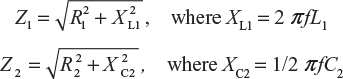
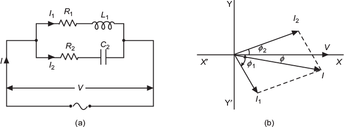
Fig. 7.47 (a) Circuit diagram (b) Phasor diagram
Step III: Determine the magnitude of current and phase angle with the voltage in each branch.
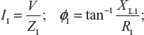 ; ɸ1
; ɸ1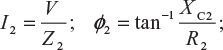 ; (lagging) (for inductive branch)
; ɸ2; (lagging) (for capacitive branch)
Step IV: Draw the phasor diagram by considering voltage as the reference phasor. Represent the branch currents on it as shown in Figure 7.47(b).
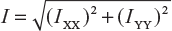
Step V: Find the phasor sum of branch currents by the method of components.
IXX = I1 cos ɸ1 + I2 cos ɸ2
IYY = − I1 sin ɸ1 + I2 sin ɸ2 (negative)
Step VI: Find the phase angle ɸ between the total current I and circuit voltage V.
![]() lagging (since IYY is negative)
lagging (since IYY is negative)
Power factor of the circuit=cosɸ(lagging)
or
![]() (lagging)
(lagging)
Example 7.30
A coil of resistance 15 Ω and inductance 0.05 H is connected in parallel with a non−inductive resistance of 20 Ω. Find (i) current in each branch of the circuit, (ii) total current supplied, (iii) phase angle and pf of combination when a voltage of 200 V at 50 Hz is applied, and (iv) power consumed in the circuit.
Solution:
The circuit is shown in Figure 7.48(a).
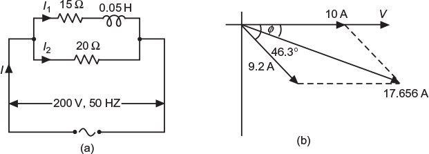
Fig. 7.48 (a) Circuit as per data (b) Phasor diagram
Applied voltage, V = 200 V; supply frequency,f = 50 Hz
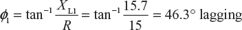
R2 = 15 Ω; XL1 = 2 π fL1 = 2π × 50 × 0.05 = 15.7 Ω
Impedance,

Current in the coil, ![]()
Phase angle,
Branch II
Resistance,
R2 = 20 Ω
Branch current,
Phase angle,
ɸ2=0(I2 is in phase with V)
The two currents are shown vectorially in Figure 7.48(b). Resolving the currents horizontally and vertically,
IXX = I2 + I1 cos ɸ1 = 10 + 9.2 cos 46.3° = 10 + 9.2 × 6,909 = 16.356 A
Iyy= 0 − I1sinɸ1= 0 − 9.2sin 46.3° = −9.2×0.723 = −6.65A
Total current supplied,

Phase angle,
Power factor of the circuit,cos ɸ = cos(−22.126°) = 0.9264(lagging)
Power,
P = VI cos ɸ = 200 × 17.659 × 0.9264 = 3,271.3W
Example 7.31
A series AC circuit has a resistance of 15 Ω and inductive reactance of 10 Ω. Calculate the value of capacitor that is connected across this series combination so that system has unity power factor. The frequency of AC supply is 50 Hz.
(U.P.T.U. 2005–06)
Solution:
The circuit is shown in Figure 7.49(a). Let the supply voltage be V V.
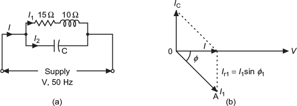
Fig. 7.49 (a) Circuit as per data (b) Phasor diagram
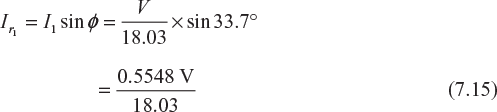
Impedance, ![]()
Current, ![]()
Power factor, ![]()
Phase angle, ɸ = cos−10.832 = 33.7° lag
Reactive component of current,
Branch II
Current drawn by the capacitor, ![]()
Power factor of the circuit will be unity when
Ic = Ir1
Now,
Example 7.32
The parallel circuit shown in Figure 7.50(a) is connected across a single phase 100 V, 50 Hz AC supply. Calculate the (i) branch currents, (ii) total current, (iii) supply power factor, and (iv) active and reactive power supplied by the supply.
(U.P.T.U. 2006−07)
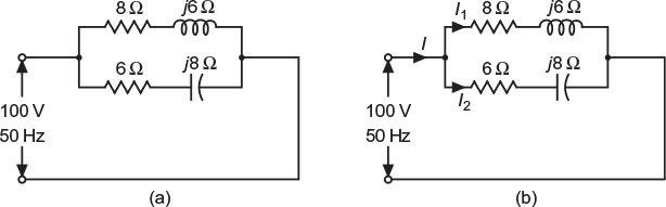
Fig. 7.50 (a) Given circuit diagram (b) Circuit as per data
V = 100 V, f = 50 Hz
- Impedance of Branch I, Z1 = 8 + j6 = 10∠36.87° ΩImpedance of Branch II, Z 2 = 6 − j8 = 10∠−53.13° ΩCurrent through Branch I,
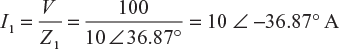 Current through Branch II,
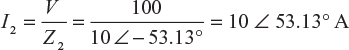
- Total current I = I1 + I2 = 10 ∠ −36.87° + 10 ∠ 53.13° = (8 − j6) + (6 + j8) = (14 + j2) A = 14.14 ∠ 8.13° A
- Supply power factor = cos ɸ = cos 8.13° = 0.989 leading
- Active power supplied by the supply, P = VI cos ɸ = 100 × 14.14 × 0.989 = 1,400 W Reactive power supplied by the supply Pr = VI sin ɸ = 100 × 14.14 sin 8.13° = 200 VAR
Example 7.33
Find the active and reactive components of current taken by a series circuit consisting of a coil of inductance 0.1 H, resistance 8 Ω, and a capacitor of 120 µF connected to a 240 V, 50 Hz supply mains. Find the value of the capacitor that has to be connected in parallel with the abovementioned series circuit so that the pf of the entire circuit is unity.
(U.P.T.U. Tut.)
Solution:
The circuit is shown in Figure 7.51(a)
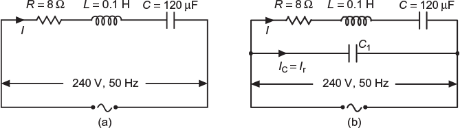
Fig. 7.51 (a) Circuit as per data (b) Circuit when C1 is connected across the given circuit
Here, R = 8 Ω; L = 0.1 H; C = 120 µF
Inductive reactance, XL = 2 πfL
= 2π× 50 × 0.1 = 31.416 Ω
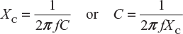
Capacitive reactance,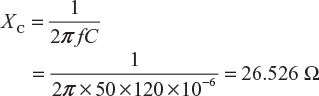
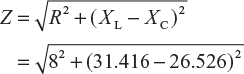
= 9.376 Ω
Circuit current, ![]() = 25.6 A
= 25.6 A
Phase angle, ![]()
Active component of current, Ia = I cos ɸ = 25.6 cos 31.435° = 21.84 A
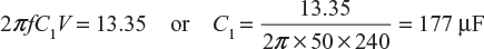
Reactive component of current, Ir = I sin ɸ = 25.6 sin 31.435° = 13.35 A (lagging)
The power factor of the whole circuit will become unity if the current drawn by the capacitor C1, connected across the series circuit, as shown in Figure 7.51(b), is made equal to the reactive (lagging) component of current of the series circuit.
that is, when
or
Example 7.34
An AC circuit includes two sections AB and BC in series. The section AB consists of two branches in parallel. The first of these is formed of resistance of 60 Ω in series with a capacitor of 50 µF, while the second consists of a resistance of 60 Ω having an inductance of 250 mH. The section BC consists of a resistance of 100 Ω having an inductance of 300 mH. The frequency of the current is 50 Hz. The voltage across section AB is 500 V. What is the voltage across the section BC?
Solution:
The circuit for the given problem is shown in Figure 7.52.
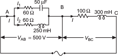
Fig. 7.52 Circuit as per data
Let us consider section AB.
Branch I
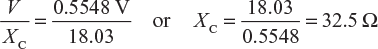
Capacitive reactance, XC = ![]()
Impedance, ![]()
Phase angle, ![]()
Branch II
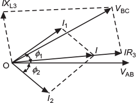
Fig. 7.53 Phasor diagram
Inductive reactance, XL2 = 2 π fL = 2π × 50 × 250 × 10−3 =78.52 Ω
Impedance, ![]()
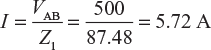
Current, 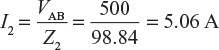
Phase angle, ![]()
The two currents I1 and I2 are shown vectorially in Figure 7.53.
Resolving the currents horizontally and vertically:
IXX = I1 cos ɸ1 + I2 cos ɸ2 = 5.72 × cos 46.7° + 5.06 × cos 52.62° = 6.9948 A
IYY = I1 sin ɸ1 − I2 sin ɸ2 = 5.72 × sin 46.7° − 5.06 × sin 52.62° = 0.142 A
Total current, ![]()
Let us consider section BC.
Inductive reactance, XL3 = 2π f L3 = 2π × 50 × 300 × 10−3 = 94.25 Ω
Impedance, ![]()
Current, I = 6.996 A
∴ Voltage across BC, VBC = IZ3= 6.996 × 137.41 = 961.35 V
Example 7.35
A single−phase motor takes 5 A current at 230 V, 50 Hz supply at a pf 0.707 lagging. It is required to improve the pf of the motor to 0.9 by connecting a capacitor in parallel with it. Determine the capacitance of capacitor.
Solution:
The circuit is shown in Figure 7.54.
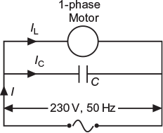
Fig. 7.54 Circuit as per data
Active component of current, Ia = Im cos ɸ1 = 5 × 0.707 = 3.535 A
Since load on the motor remains the same, the active component of current drawn by the motor remains the same.
Now, cos ɸ1 = 0.707; tan ɸ1 = tan cos−1 0.707 = 1
Reactive component of current at pf 0.707;
Ir1 = Ia tan ɸ1 = 3.535 × 1= 3.535 A
When pf = cos ɸ2 = 0.9; tan ɸ2 = tan cos−1 0.9 = 0.4843
Reactive component of current at pf 0.9;
Ir2 = Ia tan2= 3.535 × 0.4843 = 1.712 A
From phasor diagram shown in Figure 7.55, we get
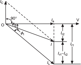
Fig.7.55 Phasor diagram
Current drawn by capacitor,
Ic=Ir1 − Ir2= 3.525 − 1.712 = 1.823 A
Now, ![]()
or ![]()
Example 7.36
A single−phase motor takes 50 A at a pf of 0.6 lagging from 250 V, 50 Hz supply. What value of capacitance must a shunt capacitor have to increase the overall power factor to 0.9?
(U.P.T.U. Tut.)
Solution:
The circuit is shown in Figure 7.56.
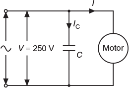
Fig. 7.56 Circuit as per data
Active component of current drawn by motor, Ia = I cos ɸ1 = 50 × 0.6 = 30 A
Initial power factor, cos ɸ1 = cos−1 0.6 lagging
tan ɸ1 = tan cos−1 0.6 = 1.333
Improved power factor, cos ɸ2 = cos−1 0.9 lagging
tanɸ2 = tan cos−1 0.9 = 0.4843
The reactive current drawn by capacitor,
IC = Ir1 − Ir2 Ia tan ɸ1 − Ia tan ɸ2
IC = Ia (tan ɸ1 − tan ɸ2) = 30 (1.333 − 0.4843) = 25.47 A
The value of capacitance required, ![]()
Example 7.37
A capacitor is placed with two inductive loads, one of 20 A at 30° lag and other of 40 A at 60° lag. What must be the current in the capacitor so that the current from the external source shall be at unity power factor?
(U.P.T.U. Tut.)
Solution:
Reactive component of current drawn by 20 A inductive load,
Ir1 = I1 sin ɸ1 = 20 sin 30° = 10 A (lagging)
Reactive component of current drawn by 40 A inductive load,
Ir2 = I2 sin ɸ2 = 40 sin 60° = 34.64 A (lagging)
The resultant power factor becomes unity only when the current drawn by the shunt capacitor becomes equal to the sum of reactive components (lagging) of current drawn by the two inductive loads.
i.e.,
Leave a Reply