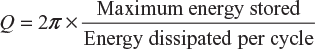
In AC circuits, the power factor may be expressed as pf = cos ɸ = R/Z = true power/apparent power
In the case of pure resistive circuit, current is in phase with circuit voltage, that is, ɸ = 0. Therefore, power factor of the circuit, cos ɸ = 1. While in the case of pure inductive or capacitive circuit, current is 90° out of phase with circuit voltage, that is, ɸ = 90°. Therefore, power factor of the circuit cos ɸ = 0. For circuits having resistance–inductance, resistance–capacitance or resistance–inductance, and capacitance, the power factor lies between 0 and 1. It may be noted that the value of pf can never be more than one.
Usually, the word lagging or leading is attached with the numerical value of pf to signify whether the current lags or leads the voltage. In inductive circuits, current always lags behind the voltage and their power factors are mentioned as lagging pf While for capacitive circuits, the power factor is mentioned as leading pf, since in these cases, current always leads the voltage vector.
7.9.1 Importance of Power Factor
The power factor of an AC circuit plays an important role in the power system. Since power of an AC circuit is given by
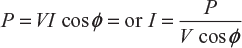
From this relation, it is clear that for fixed power at constant voltage, the current drawn by the circuit increases with a decrease in pf. Therefore, at low pf, AC circuits draw more current from their mains and results in the following disadvantages:
- Greater conductor size: At low pf, the conductors are to carry more current for the same power, and therefore, they require large area of cross−section.
- Poor efficiency: At low power factors, the conductors have to carry larger current that increases copper losses (I2R) and results in poor efficiency.
- Larger voltage drop: At low power factors, the conductors have to carry large current that increases voltage drop (IR) in the system and results in poor regulation.
- Larger kVA rating of equipment: The kVA rating of electrical machines and equipment connected in the power system such as alternators, transformers, and switch gears will be more at low power factors since it is inversely proportional to power factor (i.e., kVA = kW/cos ɸ ).
To improve the power factor of an AC circuit, a capacitor is connected across the circuit, that is, parallel to the circuit.
7.10 Q−FACTOR OF A COIL
Reciprocal of power factor of a coil is known as its Q-factor. It is also called quality factor or figure of merit of the coil.
Mathematically,
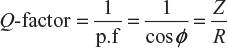
If the value of R is very small in comparison to its inductive reactance XL, then
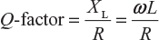
Further,
Example 7.5
A coil having a resistance of 12 Ω and an inductance of 0.1 H is connected across a 100 V, 50 Hz supply. Calculate the (i) reactance and impedance of the coil, (ii) current, (iii) phase difference between the current and the applied voltage, and (iv) power factor. Draw also the phasor diagram showing voltage and current.
Solution:
The circuit is shown in Figure 7.14.
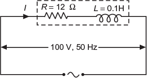
Fig. 7.14 Circuit as per data
- Reactance, XL = 2 π fL = 2 π 50 × 0.1 = 31.416 ΩImpedance,

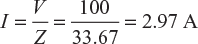
- Current,
- Phase difference,
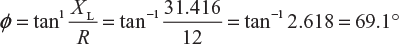
- Power factor, cos ɸ = 0.3568 lag
The phasor diagram for the circuit is shown in Figure 7.15.
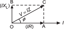
Fig. 7.15 Phasor diagram
Example 7.6
The voltage and current through a circuit element are
v = 50 sin (314 t + 55°) V
i = 10 sin (314 t + 325°) A
Find the value of power drawn by the element.
(U.P.T.U. 2006–07)
Solution:
Given
v = 50 sin (314 t + 55°) V
i = 10 sin (314 t + 325°) A
or
i = 10 sin (314 t −35°) A
Now, their phasor representation is shown in Figure 7.16.
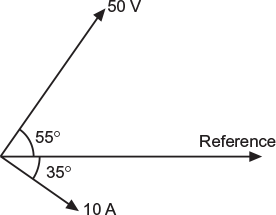
Fig. 7.16 Phasor diagram as per data
∴ Phase difference between the voltage and the current is 90°.
Now, power drawn by the circuit, P = VI cos ɸ
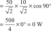
This result indicates that the element is pure inductive.
Example 7.7
A coil connected to 100 V DC supply draws 10 and the same coil when connected to 100 V, AC voltage of frequency 50 Hz draws 5 A. Calculate the parameters of the coil and power factor.
(U.P.T.U. 2004–05)
Solution:
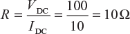
Let the resistance and inductance of the coil be R Ω and L Henry, respectively. When coil in connected to DC supply, the opposition is only resistance of the coil,
∴ Resistance of the coil,
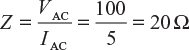
When coil is connected across AC supply of 100 V, 50 Hz, the opposition is impedance of the coil.
∴ Impedance of the coil,
Now,
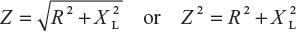
or

and
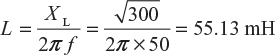
∴ Parameters are R = 10 Ω and L = 55.13 mA
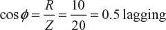
Power factor,
Example 7.8
A non−inductive resistance of 10 Ω is connected in series with an inductive coil across 200 V, 50 Hz AC supply. The current drawn by the series combination is 10 A. The resistance of the coil is 2 Ω. Determine (i) inductance of the coil, (ii) power factor, and (iii) voltage across the coil.
(U.P.T.U. 2005–06)
Solution:
The circuit as per data is shown in Figure 7.17
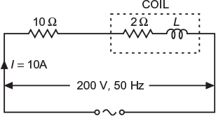
Fig. 7.17 Circuit as per data
Total impedance of the circuit, ![]()
Total resistance of the circuit, R = 10 + 2 = 12 Ω
Inductive reactance of the coil,

or
2π fL =16 or ![]()
∴ Inductance of the coil,
L = 50.93 mH
(ii) Power factor of the circuit, ![]()
(iii) Impedance of the coil, ![]() = 161.24 Ω
= 161.24 Ω
Voltage across the coil, Vc = IZc = 10 × 16.124 = 161.24 V
Power factor of the coil, 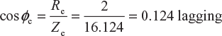 = 0.124 lagging
Example 7.9
An inductive load is connected in series with a non−inductive resistance of 8 Ω. The combination is connected across an AC supply of 100 V, 50 Hz. A voltmeter connected across the non−inductive resistor and then across the inductive load gives the reading of 64 V and 48 V, respectively. Calculate the following: (i) impedance of the load, (ii) impedance of the combination, (iii) power absorbed by the load, (iv) power absorbed by the resistor, (v) total power taken from the supply, (vi) power factor of the load, and (vii) power factor of the whole circuit.
Solution:
The circuit diagram and phasor diagram for the circuit are shown in Figures 7.18 and 7.19, respectively.
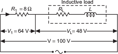
Fig. 7.18 Circuit as per data
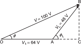
Fig. 7.19 Phasor diagram
Current in the circuit = Current in 8 Ω resistor
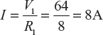
- Load impedance,
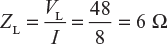
- Impedance of the combination,
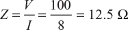 From the phasor diagram shown in Figure 7.19, we get (OB)2 = (OA)2 + (AB)2 + 2 (OA) (AB) cos ɸL ∴ Power factor of the load,
 Load resistance, RL = ZL cos ɸL = 6 × 0.586 = 3.516 Ω
 - Power absorbed by the load, PL = VL I cos ɸL = 48 × 8 × 0.586 = 225 W
- Power absorbed by the resistor R1, PR1 = I2 R1 = 8 × 8 × 8 = 512 W
- Total power taken from the supply, P = PR1 + PL = 512 + 225 = 737 W
- Power factor of the load, cos ɸL = 0.586 lag
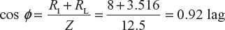
- Power factor of the whole circuit, cos ɸ
A coil of resistance 1.5 Ω and impedance 6 Ω is placed in series with a second coil of resistance 2 Ω. When a voltage of 230 V, 50 Hz is applied to the circuit, the current flowing through the circuit is 7 A. Find the inductance of the second coil.
Solution:
The circuit is shown in Figure 7.20.
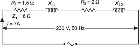
Fig. 7.20 Circuit as per data
Impedance of whole circuit,
Z = V/I = 230/7 = 32.86 Ω
Resistance of whole circuit,
R = R1 + R2 = 1.5 + 2 = 3.5 Ω
Inductive reactance,

Inductive reactance of coil I, ![]()
Inductive reactance of coil II, XL2 = X1 − XL1 = 32.67 − 5.81 = 26.86 Ω
∴ Inductance, L2 = XL2/2π f = 26.86/2 π × 50 = 85.5 mH
Example 7.11
An arc lamp (which may be regarded as being non−inductive) takes 10 A at 50 V. Calculate the impedance of choke of 1 Ω resistance to be placed in series with it in order that it may be operated at 200 V, 50 Hz supply. Find also the total power used and the power factor.
Solution:
Resistance of the arc lamp, ![]()
where
V1 = 50 V and I = 10 A
∴
Choke resistance, R2 = 1 Ω
When choke is connected, impedance of the whole circuit, ![]()
Total resistance of the circuit, R = R1 + R2 = 5 + 1 = 6 Ω
Inductive reactance of the choke, ![]()
Power factor of the circuit, cos ɸ ![]() = 0.3 lag
= 0.3 lag
Total power used, P = VI cos ɸ = 200 × 10 × 0.3 = 600 W
Leave a Reply