
Electrical power input is given to the stator. There are stator copper and iron losses and the remaining power, that is, stator output is transferred to the rotor through magnetic flux called rotor input. In the rotor, there are rotor copper losses, and the remaining power is converted into mechanical power called mechanical power developed in the rotor.
Then, there are mechanical losses, and the remaining power is available at the shaft called mechanical power output.
The power flow diagram is shown in Figure 12.18.
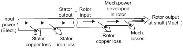
Fig. 12.18 Power flow diagram
Leave a Reply