A circuit that contains a pure resistance of R Ω, a pure inductance of L Henry, and a pure capacitor of capacitance C Farad; all connected in series is known as R–L–C series circuit.
An R–L–C series circuit is shown in Figure 7.28.
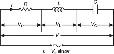
Fig. 7.28 Circuit containing resistance, inductance and capacitance in series
Here, XL = 2 π ɸ L and XC = 1/2 π f C
When a resulting current I (rms value) flows through the circuit, the voltage across each component will be
VR = IR, that is, voltage across R……….. in phase with I;
VL = IXL, that is, voltage across L……….. leads I by 90°;
VC = IXC, that is, voltage across C……….. lags I by 90°;
The phasor diagram is shown in Figure 7.29, where current is taken as the reference phasor. Since voltage across inductance VL leads the current vector I by 90° and voltage across capacitance VC lags the current vector I by 90°, they act opposite to each other. If VL > VC, in effect, the circuit behaves as an inductive circuit; however, when VL < VC, the circuit behaves as a capacitive circuit. Here, the phasor diagram is drawn for an inductive circuit (i.e., when VL > VC).
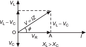
Fig. 7.29 Phasor diagram

or
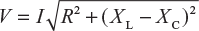
or
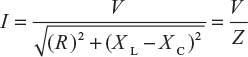
where ![]() is the total opposition offered to the flow of AC by an R–L–C series circuit and is called impedance of the circuit.
is the total opposition offered to the flow of AC by an R–L–C series circuit and is called impedance of the circuit.
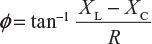
7.12.1 Phase Angle
From phasor diagram: ![]()
or
7.12.2 Power
Average power, P = VI cos ɸ = I2 R
Power factor, ![]()
The alternating voltage applied across the circuit is given by
v = Vm sin ω t,
Therefore, the circuit current is represented by the equation as per the constants or parameters, as explained in the following three cases of R–L–C series circuit:
- When XL > XC, the phase angle ɸ is positive. In effect, the circuit behaves as an R–L series circuit. The circuit current lags behind the applied voltage and pf is lagging. The current is given by the equation. i = Im sin (ω t − ɸ)
- When XL < XC, the phase angle ɸ is negative. In effect, the circuit behaves as an R–C series circuit. The circuit current leads the applied voltage and pf is leading. The current is given by the equation. i = Im sin (ω t + ɸ)
- When XL = XC, the phase angle ɸ is zero. In effect, the circuit behaves like a pure resistive circuit. The circuit current is in phase with applied voltage and pf is unity. The current is given by the equation. i = Im sin ω t
7.12.3 Impedance Triangle
Figure 7.30(a) shows the impedance triangle of the circuit when XL > XC, while Figure 7.30(b) shows the impedance triangle of the circuit when XL < XC.
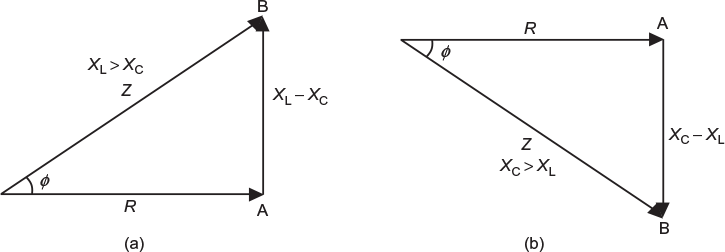
Fig. 7.30 (a) Impedance triangle (XL > XC) (b) Impedance triangle (XC > XL)
Leave a Reply