
The revolving magnetic field set up in the stator by polyphase currents is common to both stator and rotor winding. This field induces emfs in both windings. The stator-induced emf per phase is given by the relation
E1 = 4.44 × kw1 × T1 × f × ɸm (12.1)
Where kw1 = winding factor, that is, product or coil span factor kc and distribution factor kd.
T1 = No. of turns/phase of stator winding
ƒ= stator or supply frequency and
ɸm= maximum value of flux.
The rotor-induced emf/phase, E2 = 4.44 × kw2 × T2× ƒr × ɸm (12.2)
Where ƒr is the rotor current frequency, and under stationary condition, that is, at the start ƒr= ƒ.
Therefore, rotor-induced emf/phase at standstill or start, E2s= 4.44 × kw2 × T2 × f × ɸm
Dividing equation (12.2) by (12.1), we get,
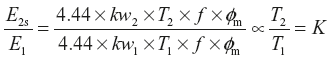 (i.e., transformation ratio)
From equation (12.2), induced emf in the rotor under running condition,
E2 = 4.44 × kw2 × T2 × (S × f ) × ɸm = S × E2s
The induced emf in the rotor circuit is maximum at the start and varies according to the value of slip under running condition. Since the value of normal slip under loaded condition is nearly 5 per cent, the rotor-induced emf is, therefore, nearly 5 per cent of the maximum value.
Leave a Reply