All the transformers are tested before placing them in the field. By performing these tests, we can determine the parameters of a transformer to compute its performance characteristics (like voltage regulation and efficiency.).
To furnish the required information, open circuit and short circuit tests are conducted conveniently without actually loading the transformer.
10.23.1 Open-circuit or No-load Test
This test is carried out to determine the no-load loss or core loss or iron loss and no-load current I0 which is helpful in finding the no-load parameters, that is, exciting resistance R0 and X0 exciting reactance of the transformer.
This test is usually carried out on the low-voltage side of the transformer, that is, a watt meter W, a voltmeter V, and an ammeter A are connected in low-voltage winding (say primary). The primary winding is then connected to the normal rated voltage V1 and frequency as given on the name plate of the transformer. The secondary side is kept open or connected to a voltmeter V′ as shown in Figure 10.31(a). Since the secondary (high-voltage winding) is open circuited, the current drawn by the primary is called no-load current I0 measured by the ammeter A. The value of no-load current I0 is very small usually 2 to 10% of the rated full-load current. Thus, the copper loss in the primary is negligibly small and no copper loss occurs in the secondary as it is open. Therefore, wattmeter reading W0 only represents the core or iron losses for all practical purposes. These core losses are constant at all loads. The voltmeter V′ if connected on the secondary side measures the secondary induced voltage V2.
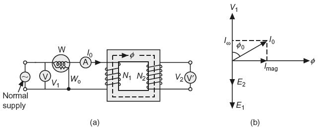
Fig. 10.31 (a) Circuit for open circuit test (b) Phasor diagram at no-load
The ratio of voltmeter readings, ![]() gives the transformation ratio of the transformer. The phasor diagram of transformer at no-load is shown in Figure 10.31(b).
gives the transformation ratio of the transformer. The phasor diagram of transformer at no-load is shown in Figure 10.31(b).
Let the wattmeter reading = W0
voltmeter reading = V1
and ammeter reading = I0
Then, iron losses of the transformer Pi = W0
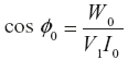
that is, V1I0 cos ɸ0 = W0
No-load power factor,
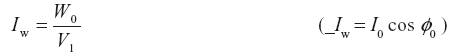
Working component,
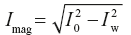
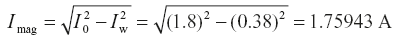
Magnetising component
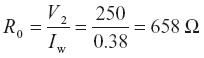
No-load, parameters, that is, Equivalent exciting resistance, 
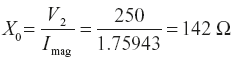
Equivalent exciting reactance, 
The Iron losses measured by this test are used to determine transformer efficiency and parameters of exciting circuit of a transformer shown in Figure 10.32.
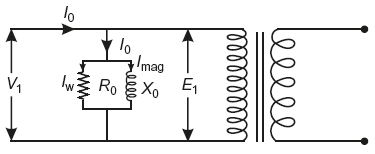
Fig. 10.32 Transformer at no-load with exciting circuit
10.23.2 Short Circuit Test
This test is carried out to determine the following:
- Copper losses at full load (or at any desired load). These losses are required for the calculations of efficiency of the transformer.
- Equivalent impedance (Zes or Zep), resistance (Res or Rep) and leakage reactance (Xes or Xep) of the transformer referred to the winding in which the measuring instruments are connected. Knowing equivalent resistance and reactance, the voltage drop in the transformer can be calculated and hence regulation of transformer is determined.
This test is usually carried out on the high-voltage side of the transformer, that is, a wattmeter W, voltmeter V, and an ammeter A are connected in high-voltage* winding (say secondary). The other winding (primary) is then short circuited by a thick strip or by connecting an ammeter A′ across the terminals as shown in Figure 10.33. A low voltage at normal frequency is applied to the high-voltage winding with the help of on autotransformer so that full-load current flows in both the windings, measured by ammeters A and A′. Low voltage is essential, failing which an excessive current will flow in both the windings that may damage them.
Since a low voltage (usually 5 to 10% of normal rated voltage) is applied to the transformer winding, therefore, the flux set-up in the core is very small about ![]() th to
th to ![]() th of normal flux.
th of normal flux.
The iron losses are negligibly small due to low value of flux as these losses are approximately proportional to the square of the flux. Hence, wattmeter reading Wc only represents the copper losses in the transformer windings for all practical purposes. The applied voltage V2sc is measured by the voltmeter V which circulates the current I2sc (usually full-load current) in the impedance Zes of the transformer to the side in which instruments are connected as shown in Figure 10.33.
Let the wattmeter reading = Wc
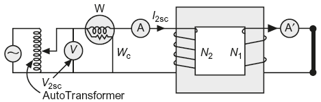
Fig. 10.33 Circuit for short circuit test
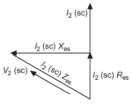
Fig. 10.34 Phasor diagram at short circuit
voltmeter reading = V2sc
and ammeter reading = I2sc
Then, full-load copper losses of the transformer,
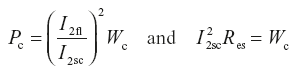
Equivalent resistance referred to secondary, 
From phasor diagram as shown in Figure 10.34
I2sc Zes = V2sc
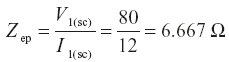
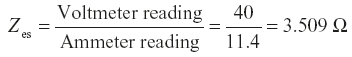
∴Equivalent impedance referred to secondary, Zes = V2sc/I2sc
Equivalent reactance referred to secondary, ![]()
After calculating Res and Xes, the voltage regulation of the transformer can be determined at any load and power factor.
Example 10.35
Open-circuit and short-circuit tests were conducted on a 50 kVA, 6360/240 V, 50 Hz, single-phase transformer in order to find its efficiency. The observations during these tests are as follows:
O.C. test: Voltage across primary winding = 6360 V; primary current = 1.0 A, and power input = 2 kW.
S.C. test: Voltage across primary = 180 V; current in secondary winding = 175 A, and power input = 2 kW.
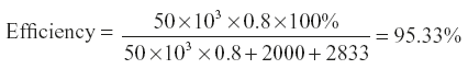
Calculate the efficiency of the transformer, when supplying full load at p.f. of 0.8 lagging.
(A.U.)
Solution:
O.C. test:
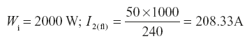
S.C.test:
I2sc = 175 A; Wc = 2000 W
∴ Cu loss at full load, 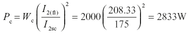
∴
Example 10.36
A 15 kVA, 440/230 V, 50 Hz, single-phase transformer gave the following test results:
| Open Circuit (L.V. side) | 250 V, 1.8 A, 95 W. |
| Short circuit test (H.V. side) | 80 V, 12.0 A, 380 W. |
Compute the parameters of the equivalent circuit referred to L.V. side.
(P.T.U. May 2005)
Solution:
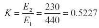
Transformer rating = 15 kVA; E1 = 440 V; E2 = 230 V; f = 50 Hz
Open circuit test (L.V. side); V2 = 250 V; I0 = 1.8 A; W0 = 95 W
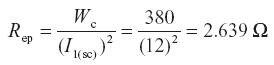
Short-circuit test (H.V. side); V1(sc) = 80 V; I1(sc) = 12 A; Wc = 380 W
From open-circuit test performed on L.V. side
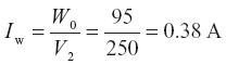
Exciting resistance,
Exciting reactance,
From short-circuit test performed on H.V. side

Transformer resistance and reactance referred to L.V. (secondary) side
Res = Rep × K2 = 2.639 × (0.5227)2 = 0.7211 Ω
Xes = Xep × K2 = 6.122 × (0.5227)2 = 1.673 Ω
Example 10.37
The following test data are obtained on a 5 kVA, 220/440 V single-phase transformer; O.C. test −220 V, 2 A, 100 W on L.V. side; S.C. test − 40 V. 11.4 A, 200 W on H.V. side. Determine the percentage efficiency and regulation at full load 0.9 p.f. lag.
Solution:
From O.C. test, Iron losses, Pi = 100 W
From S.C. test, Copper losses, Wc = 200 W (at the load at which test is performed)
Full-load current on H.V. side, 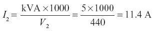
that is, S.C test is performed at full load since I2sc = I2
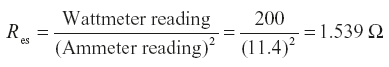
Full-load copper loss, Pc = Wc = 200 W
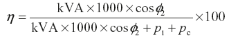
Efficiency,
From S.C. test:

Here cos ɸ2 = 0.9; sin ɸ2 = sin cos−1 0.9 = 0.4359
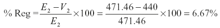
E2 = V2 + I2 Res cos ɸ2 + I2Xessin ɸ2
= 440 + 11.4 × 1.539 × 0.9 + 11.4 × 3.153 × 0.4359 = 471.46 V
Example 10.38
The O.C. and S.C. tests on a 5 kVA, 230/160 V, 50 Hz, transformer gave the following data.
O.C. test (H.V. side) − 230 V, 0.6 A, 80 watt
S.C. test (L.V. side) − 6 V, 15 A, 20 watt
Calculate the efficiency of transformer on full load at 0.8 p.f. lagging.
(P.U. June, 1996)
Solution:
From open circuit test, iron losses, Pi = 80 W
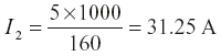
As short-circuit test is performed on L.V. side, I2sc = 15 A
Full-load secondary current,
Copper losses measured at S.C. test, Wc = 20 W
Full-load copper losses, 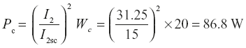
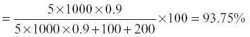
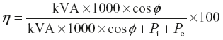
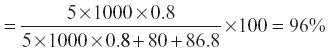
Efficiency of transformer at full load 0.8 p.f. lagging
Example 10.39
The following results were obtained on a 50 kVA transformer:
- Open-circuit tests: Primary voltage 3300 V, secondary voltage 415 V, power 430 W
- Short-circuit test: Primary voltage 124 V, primary current 15.3 A, primary power 525 W secondary current full-load value.
Calculate:
- The efficiency at full load and at half load for 0.7 power factor.
- The voltage regulation for power factor 0.7: (i) lagging (ii) leading
- The secondary terminal voltages corresponding to (a) and (b)
(P.T.U. Dec. 2007)
Solution:
Rating of transformer = 50 kVA; Power factor = 0.7
Open-circuit test (primary): V1 = 3300 V; V2 = 415 V; W0 = 430 W
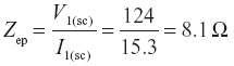
Short-circuit test (primary): V1(SC) = 124 V; I1(SC) = 15.3 A; Wc = 525 W
Short-circuit test is performed at full-load secondary current,
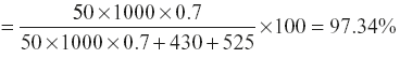
∴ Full-load copper losses,
Pc = Wc = 525 W
Iron losses,
Pi = W0 = 430 W
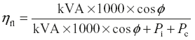
- Full − load efficiency,
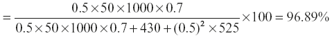
 Efficiency at half load,
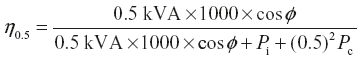
- Transformer impedance referred to primary,
 Transformer resistance referred to primary,
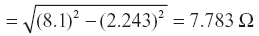
 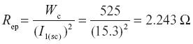 Transformer reactance referred to primary,
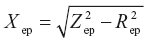
 At 3300 V, primary full-load current,
 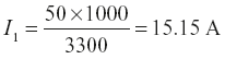 For p.f., cos ɸ = 0.7 lag; sin ɸ = sin cos−10.7 = 0.714E1 = V1 − I1 Rep cos ɸ − I1Xcp sin ɸ= 3300 − 15.15 × 2.243 × 0.7 − 15.15 × 7.783 × 0.714= 3300 − 23.787 − 84.189 = 3192 V
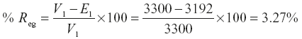 For p.f., cos ɸ = 0.7 leading; sin ɸ = sin cos−10.7 = 0.714
 = V1− I1 Repcos ɸ + I1 Xcp sin ɸ= 3300 − 15.15 × 2.243 × 0.7 + 15.15 × 7.783 × 0.714= 3300 − 23.787 + 84.189 = 3360 V
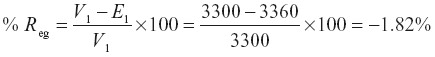
- Secondary terminal voltage at 0.7 p.f. lagging:
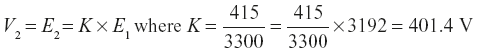 Secondary terminal voltage at 0.7 p.f. leading
Leave a Reply