
The two-wattmeter method can be explained somewhat more clearly by considering a balanced load. In this case, we shall prove that power measured by the two wattmeters (i.e.,sum of two wattmeter readings) is equal to ![]() VLIL cosɸ, which is the actual power consumed in a three- phase balanced load.
VLIL cosɸ, which is the actual power consumed in a three- phase balanced load.
The connection diagram for a three-phase balanced load (connected in star) is shown in Figure 8.37(a). Considering load to be an inductive one, the phasor diagram is shown in Figure 8.37(b). The three-phase voltages VRN, VYN,and VBNdisplaced by an angle of 120° electrical are shown in phasor diagram. The phase currents lag behind their respective phase voltages by an angle ɸ.
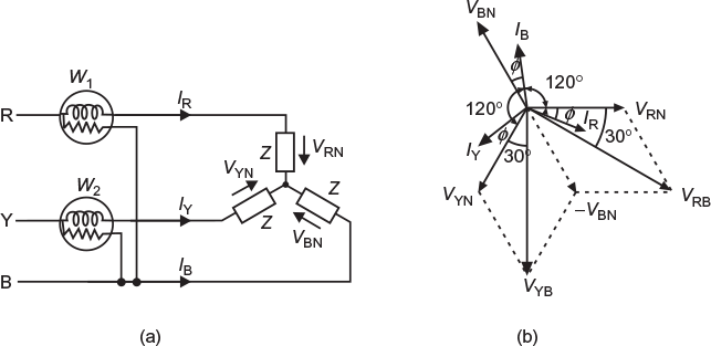
Fig. 8.37 (a) Connection of two wattmeters for power measurement in balanced 3-phase load (b) Phase diagram
Current through current coil (c.c.) of W1 = IR
Potential difference across potential coil (p.c.) of ![]()
To obtain VRB, reverse the phasor VBNand add it vectorially to phasor VRN, as shown in Figure 8.37(b).
The phase difference between VRBand IRis (30° − ɸ).
Power measured by wattmeter
W1 = VRBIR cos(30 − ɸ)
Current through c.c. of W2 = IY
Potential difference across p.c. of ![]()
To obtain VYB, reverse the phasor VBNand add it vectorially to phasor VYNas shown in Figure 8.37(b).
The phase difference between VYBand IYis (30° + ɸ).
Power measured by wattmeter, W2 = VYB= VBR= VL
Wattmeter reading, W1 = VL ILcos (30° − ɸ)
Wattmeter reading, W2 = VL ILcos (30° + ɸ)
Sum of the two wattmeter readings,
W1 + W2 = VL ILcos (30° − ɸ) + VL ILcos (30° + ɸ)
= VL IL[cos (30° − ɸ) + cos (30° + ɸ)]
= VL IL[cos 30° cos ɸ+ sin 30° sin ɸ+ cos 30° cos ɸ− sin 30° sin ɸ]
= VL IL(2 cos 30° cosɸ ) 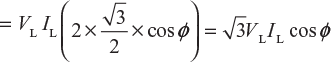
= Total power absorbed by a three-phase balanced load (P)
P = W1 + W2
Thus, the sum of the readings of the two wattmeters is equal to the power absorbed in a three-phase balanced load.
8.16.1 Determination of Power Factor from Wattmeter Readings
We have seen that
W1 + W2 = ![]() VLILcosɸ (8.1)
VLILcosɸ (8.1)
W1 − W2 = VLIL(cos(30° − ɸ) − cos(30° + ɸ))
=2VLILsin30sinɸ= VLILsinɸ (8.2)
Dividing Equation (8.2) by (8.1), we get
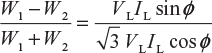
or
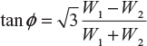
Power factor
cosɸ = cos tan−1ɸ = 
8.16.2 Determination of Reactive Power from Two Wattmeter Readings
Multiplying Equation (8.2) by ![]() , we get
, we get
![]() (W1 − W2) =
(W1 − W2) = ![]() VLILsinɸ = Pr
VLILsinɸ = Pr
Reactive power,
Pr = ![]() (W1 − W2)
(W1 − W2)
8.17 EFFECT OF POWER FACTOR ON THE TWO WATTMETER READINGS
For lagging power factor, the wattmeter readings are
W1 = VL ILcos (30° − ɸ) and W2 = VL ILcos (30° + ɸ)
It is clear that the readings of the two wattmeters do not only depend upon load, but they also depend upon the phase angle ɸor the power factor of the load.
Leave a Reply