The concepts of NAND, AND, NOR, and OR are relatively easy to understand because they map onto the way we think in everyday life. For example, a textual equivalent of a NOR could be: “If it’s windy or if it’s raining then I’m not going out.” By comparison, the concepts of XOR and XNOR can be a little harder to grasp because we don’t usually consider things in these terms. A textual equivalent of an XOR could be: “If it iswindy and it’s not raining, or if it’s not windy and it is raining, then I will go out.” Although this does make sense (in a strange sort of way), we don’t often find ourselves making decisions in this manner.
For this reason, it is natural to assume that XNOR and XOR gates would be a little more difficult to construct. However, these gates are full of surprises, both in the way in which they work and the purposes for which they can be used. For example, a 2-input XNOR can be implemented using only four transistors (Figure 10.28). Unlike AND, NAND, OR, and NOR gates, there are no such beasts as XNOR or XOR primitives with more than two inputs. However, equivalent functions with more than two inputs can be formed by connecting a number of 2-input primitives together.
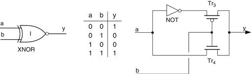
Figure 10.28 CMOS implementation of a 2-input XNOR gate
The NOT gate would be constructed in the standard way using two transistors as described above, but the XNOR differs from the previous gates in the way that transistors Tr3 and Tr4 are utilized. First, consider the case where input b is presented with a logic 0: transistor Tr4 is turned OFF, transistor Tr3 is turned ON, and output y is connected to the output of the NOT gate via Tr3. Thus, when input b is logic 0, output y has the inverse of the value on input a. Now consider the case where input b is presented with a logic 1: transistor Tr3 is turned OFF, transistor Tr4 is turned ON, and output y is connected to input a via Tr4. Thus, when input b is logic 1, output y has the same value as input a. The end result of all these machinations is that wiring the transistors together in this way does result in a function that satisfies the requirements of the XNOR truth table.
Unlike the other complementary gates, it is not necessary to invert the output of the XNOR to form an XOR (although we could if we wanted to, of course). A little judicious rearranging of the components results in a 2-input XOR that also requires only four transistors (Figure 10.29).
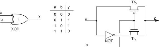
Figure 10.29 CMOS implementation of a 2-input XOR gate
First, consider the case where input b is presented with a logic 0: transistor Tr4 is turned OFF, transistor Tr3 is turned ON, and output y is connected to input a via Tr3. Thus, when input b is logic 0, output y has the same value as input a. Now consider the case where input b is presented with a logic 1: transistor Tr3 is turned OFF, transistor Tr4 is turned ON, and output y is connected to the output of the NOT gate via Tr4. Thus, when input b is logic 1, output y has the inverse of the value on input a. Once again, this results in a junction that satisfies the requirements of the XOR truth table.
Leave a Reply