
The use of operational amplifiers in active filter devices is now well established in communications systems. Their main advantages over passive filters are:
(a) flexibility in design and construction;
(b) the absence of inductors, which at low frequencies is useful due to their large size and cost;
(c) low-frequency applications down to 1 Hz;
(d) the buffering effect due to the high input impedance and the low output impedance;
(e) with gain setting resistors the op-amp is capable of providing gain; hence, the input signal is not attenuated as it is in passive filters;
(f) they are easier to tune than passive filters.
It is as well at this stage to appreciate that there are many types of filter, such as crystal, acoustical and digital filters, all of which have a specific application. In this chapter we will investigate active filters which are of the analog type but can be used in either digital or analog system applications.
17.3.1 Filter Response
Associated with a filter’s performance is the frequency response, which involves a plot of frequency against gain or against attenuation. This graph involves a response for all frequencies which the filter is designed to pass. At a particular frequency, known as the cut-off frequency, the response starts to decrease in amplitude. This is known as the roll-off and is a measure of how sharply the filter responds to attenuate frequencies above or below the cut-off frequency.
The filters in this chapter will have input RC networks, and as the signal frequency decreases the capacitive reactance Xc increases. This causes less voltage to be applied across the input impedance of the amplifier because more is dropped across Xc. This reduces the overall gain of the filter, and a critical point is reached when the output voltage is 0.707, i.e., ![]() , of the input (V0=0.707 Vi). This condition occurs when Xc=R and is called the –3 dB point of the response as the overall gain is 3 dB down on the pass-band gain. The frequency at which this occurs is the cut-off frequency. This discussion applies to all filter types.
, of the input (V0=0.707 Vi). This condition occurs when Xc=R and is called the –3 dB point of the response as the overall gain is 3 dB down on the pass-band gain. The frequency at which this occurs is the cut-off frequency. This discussion applies to all filter types.
All filters have four basic applications which can be easily understood from the ideal responses shown below. Note that an ideal response is one which has a vertical roll-off at the cut-off frequency. In practice this is not possible, but certain sophisticated filters tend to approach it. The four ideal configurations are shown in Figure 17.4, in which the pass and stop bands are shown.
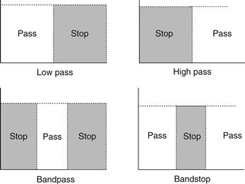
Figure 17.4 The four ideal filter configurations
17.3.2 Cut-off Frequency and Roll-off Rate
As has been mentioned, no filter achieves the ideal response shown in Figure 17.4, but the higher the order of the filter the closer it approaches the ideal case. This is shown in Figure 17.5, which shows a multiple response diagram. It can be seen from this diagram that the roll-off rate increases with the order of the filter. This filter order is dependent on the number of RC networks (number of poles) included in the filter design. For example, if a single RC network is used with a filter it is referred to as a single-pole filter, while two RC networks produce a two-pole filter. Correspondingly, the roll-off would be 20 dB/ decade and 40 dB/decade, respectively. Hence, increasing the number of RC networks increases the order of the filter. A three-pole or third-order filter is shown in Figure 17.6.
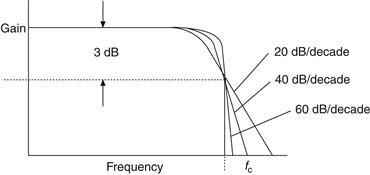
Figure 17.5 Multiple response diagram
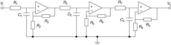
Figure 17.6 Third-order filter
It is normally not necessary to go beyond a fourth-order filter, but if this situation arises then it is a simple matter of cascading first and second-order filters to achieve higher orders. We will now examine these two important filters in detail and see how they can be realized in a practical way.
17.3.3 Filter Types
There are two fundamental responses generally used in the design of filters; these are referred to as the Butterworth and Chebyshev responses. The low-pass filter responses for these types are shown in Figure 17.7. As can be seen, the two responses are quite different. The Butterworth type has what is called a maximally flat response in the pass band. Hence, there is no ripple in this type of filter and the cut-off frequency is generally taken at the 3 dB level as shown. Note that in Figure 17.7(a) the stop band lies between 0 Hz and fc. In practice this may not be the case, and a minimum gain may be stipulated (say) between point A and fc.
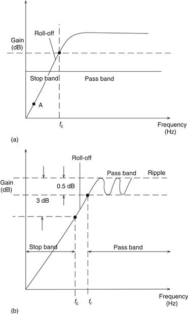
Figure 17.7 (a) Butterworth filter; (b) Chebyshev filter
The maximally flat response of the Butterworth is good at frequencies around about zero hertz, but the response is poorer near the edge of the pass band. The Chebyshev filter can solve this problem. The Chebyshev response shown in Figure 17.7(b) contains a ripple in the pass band. However, the attenuation increases more rapidly outside the pass band than the Butterworth. The greater the ripple, the more selective is the filter. The pass band is not so easily defined but is usually taken from the point where the highest-frequency peak ripple occurs. If, for example, the Chebyshev high-pass filter in Figure 17.7(b) has a 0.5 dB ripple as shown and fr=1 kHz, then its response would be given as±0.5 dB from 1 kHz onwards with a rapidly increasing attenuation for frequencies less than 1 kHz. However, in some applications the 3 dB bandwidth is required as shown at point C on Figure 17.7(b), and this may be calculated using what are called transfer functions. These will be discussed later.
17.3.4 Filter Orders
Filter orders have already been mentioned, and it can be seen from Figure 17.4 that the orders would have to be infinitely high in order to achieve ideal responses.
The order of a Chebyshev or Butterworth filter determines the sharpness or roll-off of the response, but the interpretation of order is slightly different because of the ripple pass band in the Chebyshev filter. In this case the number of ripple peaks in the pass band determines the order (n) of the filter. This is shown in Figure 17.8. For example, in Figure 17.8(a)n=2 and in Figure 17.8(c)n=4. Note that unlike the Chebyshev filter, the Butterworth low-pass filter will be 3 dB down on its maximum value no matter what the order is. The same points apply to the high-pass filter responses.
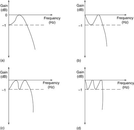
Figure 17.8 Filter roll-off
Leave a Reply