As with series circuits, parallel networks may be analyzed by using phasor diagrams. However, with parallel networks containing more than two branches, this can become very complicated. It is with parallel AC network analysis in particular that the full benefit of using complex numbers may be appreciated. The theory for parallel AC networks introduced previously is relevant; more advanced networks will be analyzed in this chapter using j notation. Before analyzing such networks admittance, conductance and susceptance are defined.
7.6.1 Admittance, Conductance and Susceptance
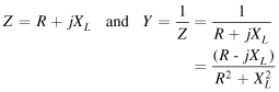
Admittance is defined as the current I flowing in an AC circuit divided by the supply voltage V (i.e., it is the reciprocal of impedance Z). The symbol for admittance is Y. Thus,

The unit of admittance is the siemen, S.
An impedance may be resolved into a real part R and an imaginary part X, giving Z=R±jX. Similarly, an admittance may be resolved into two parts—the real part being called the conductance G, and the imaginary part being called the susceptance B—and expressed in complex form. Thus, admittance,

When an AC circuit contains:
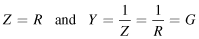
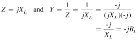
thus, a negative sign is associated with inductive susceptance, BL.
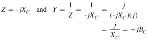
thus, a positive sign is associated with capacitive susceptance, BC
(d) resistance and inductance in series, then,
i.e.,
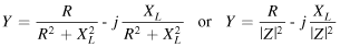
Thus, conductance, G=R/|Z|2 and inductive susceptance, BL=-XL/|Z|2
(Note that in an inductive circuit, the imaginary term of the impedance, XL, is positive, whereas the imaginary term of the admittance, BL, is negative.)
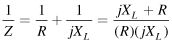
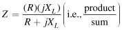
(e) resistance and capacitance in series, then,
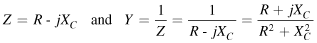
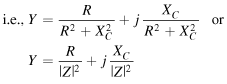
Thus, conductance, G=R/|Z|2 and capacitive susceptance, BC=XC/|Z|2
(Note that in a capacitive circuit, the imaginary term of the impedance, XC, is negative, whereas the imaginary term of the admittance, BC, is positive.)
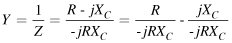
(a) resistance and inductance in parallel, then,
from which,
and,
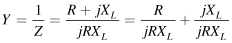
i.e.,
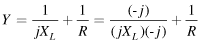
or,

Thus, conductance, G=1/R and inductive susceptance, BL=–1/XL.
(b) resistance and capacitance in parallel, then,

and
i.e.,
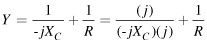
or,

Thus, conductance, G =1/R and capacitive susceptance, BC =l/XC
The conclusions that may be drawn from sections (d) to (g) above are:
(i) that a series circuit is more easily represented by an impedance,
(ii) that a parallel circuit is often more easily represented by an admittance especially when more than two parallel impedances are involved.
Example 7.11
Determine the admittance, conductance and susceptance of the following impedances: (a) –j5 Ω (b) (25+j40) Ω (c) (3 –j2) Ω (d) 50∠40°Ω.
Solution
.
(a) If impedance Z=–j5 Ω, then,
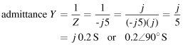
Since there is no real part, conductance, G =0, and capacitive susceptance, BC =0.2 S.
(b) If impedance Z=(25+j40) Ω then,
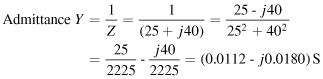
Thus, conductance, G =0.0112 S and inductive susceptance, BL=0.0180 S.
(c) If impedance Z=(3 –j2) Ω, then,
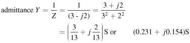
Thus, conductance, G =0.231 S and capacitive susceptance, BC =0.154 S
(d) If impedance Z=50∠40 Ω, then,
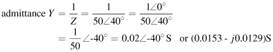
(0.0153 –j0.0129) S
Thus, conductance, G=0.0153 S and inductive susceptance, BL=0.0129 S.
Example 7.12
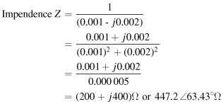
Determine expressions for the impedance of the following admittances: (a) 0.004∠30 S (b) (0.001 –j0.002) S (c) (0.05+j 0.08) S.
Solution
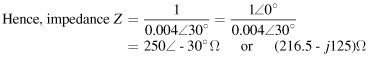
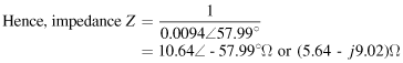
(a) Since admittance Y=1/Z, impedance Z=1/Y.
(c) Admittance Y=(0.05+j0.08) S=0.094∠57.99 S
Example 7.13
The admittance of a circuit is (0.040+j0.025) S. Determine the values of the resistance and the capacitive reactance of the circuit if they are connected (a) in parallel, (b) in series. Draw the phasor diagram for each of the circuits.
Solution
Admittance Y=(0.040+j0.025) S, therefore conductance, G=0.040 S and capacitive susceptance, BC=0.025 S. From equation (7.1) when a circuit consists of resistance R and capacitive reactance in parallel, then Y=(1/R)+(j/XC).
Hence, resistance ![]()
and capacitive reactance ![]()
The circuit and phasor diagrams are shown in Figure 7.14.
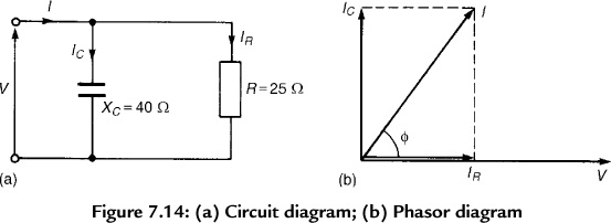
Figure 7.14 (a) Circuit diagram; (b) Phasor diagram
Admittance Y=(0.040+j0.025) S, therefore,
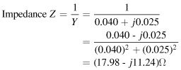
Thus, the resistance, R=17.98 Ω and capacitive reactance, XC=11.24 Ω
The circuit and phasor diagrams are shown in Figure 7.15.
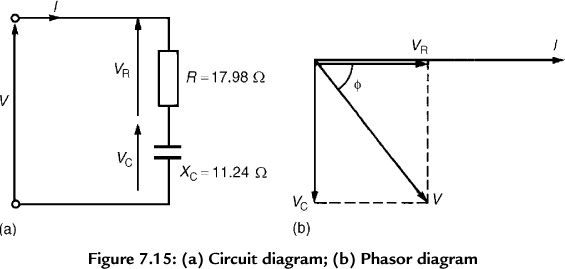
Figure 7.15 (a) Circuit diagram; (b) Phasor diagram
The circuits shown in Figs. 7.14(a) and 7.15(a) are equivalent in that they take the same supply current I for a given supply voltage V; the phase angle ϕ between the current and voltage is the same in each of the phasor diagrams shown in Figs. 7.14(b) and 7.15(b).
7.6.2 Parallel AC Networks
Figure 7.16 shows a circuit diagram containing three impedances, Z1, Z2 and Z3 connected in parallel. The potential difference across each impedance is the same, i.e., the supply voltage V. Current I1=V/Z1, I2=V/Z2 and I3=V/Z3. If ZT is the total equivalent impedance of the circuit then I=V/ZT. The supply current, I=I1+I2+I3 (phasorially).
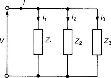
Figure 7.16 Circuit with three impedances in parallel
Thus, ![]() and,
and,
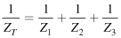
or total admittance, YT=Y1+Y2+Y3
In general, for n impedances connected in parallel, ![]() (phasorially)
(phasorially)
It is in parallel circuit analysis that the use of admittance has its greatest advantage.
7.6.2.1 Current Division in AC Circuits
For the special case of two impedances, Z1 and Z2, connected in parallel (see Figure 7.17),
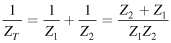
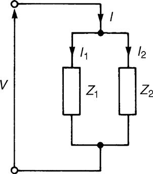
Figure 7.17 Two impedances connected in parallel
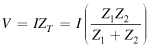
The total impedance, ZT =Z1Z2/(Z1+Z2) (i.e., product/sum).
From Figure 7.17,
supply voltage,
Thus,
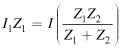
i.e.,
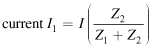
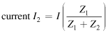
Similarly,
Note that all of the above circuit symbols infer complex quantities either in Cartesian or polar form.
The following problems show how complex numbers are used to analyze parallel AC networks.
Example 7.14
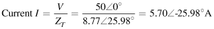
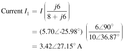
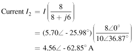
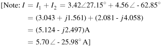
Determine the values of currents I, I1 and I2 shown in the network of Figure 7.18.
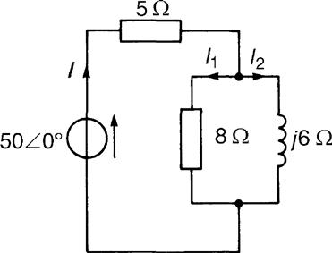
Figure 7.18 Network for Example 7.14
Solution
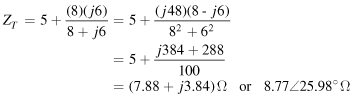
Total circuit impedance,
Example 7.15
For the parallel network shown in Figure 7.19, determine the value of supply current I and its phase relative to the 40 V supply.
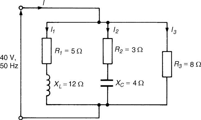
Figure 7.19 Parallel network for Example 7.15
Solution
Impedance Z1=(5+j12) Ω, Z2=(3 –j4) Ω and Z3=8 Ω Supply current ![]() where ZT=total circuit impedance, and YT=total circuit admittance.
where ZT=total circuit impedance, and YT=total circuit admittance.
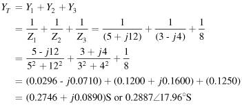
i.e., YT=(0.2746+j0.0890) S or 0.2887∠17.96 S

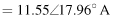
Hence, the currentIis 11.55A and is leading the 40 V supply by 17.96°.
Alternatively, current I=I1+I2+I3
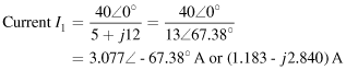
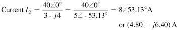
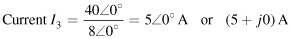
Thus,![]()

Example 7.16
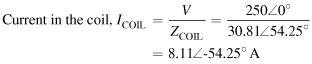
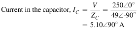
An AC network consists of a coil, of inductance 79.58 mH and resistance 18 Ω, in parallel with a capacitor of capacitance 64.96 μF. If the supply voltage is 250∠0 V at 50 Hz, determine (a) the total equivalent circuit impedance, (b) the supply current, (c) the circuit phase angle, (d) the current in the coil, and (e) the current in the capacitor.
Solution
The circuit diagram is shown in Figure 7.20.
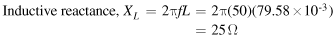
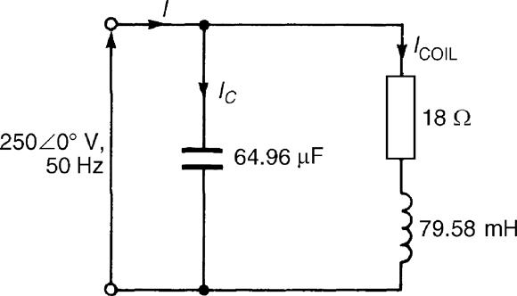
Figure 7.20 Circuit diagram for Example 7.16
Hence, the impedance of the coil,

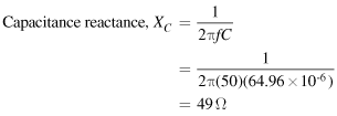
In complex form, the impedance presented by the capacitor ZC is –jXC, i.e., –j49 Ω or 49∠–90°Ω.
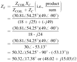
(a) Total equivalent circuit impedance,
(b)
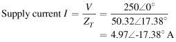
(c) Circuit phase angle=17.38 lagging, i.e., the current I lags the voltage V by 17.38.
Leave a Reply