
Previously we have looked at single low- or high-pass filters, but a common application of filters is where a band of frequencies has to be passed while all other frequencies are stopped. This is called a bandpass filter. Such a filter may be formed from a low- and a high-pass filter in cascade. Generally the low pass is followed by the high pass, but the order of cascade is not important as the same result will be produced.
Consider Figure 17.26. The following points should be noted from this diagram.
1. A second-order low-pass filter is cascaded with a second-order high-pass filter. Note that the labelling of the components should correspond with the normalized tables.
2. The gain of the low-pass filter is unity, while that of the high pass filter is 2. This gives an overall gain of 2.
3. The overall response will give two cut-off frequencies.
4. No buffering is required as op-amps are used.
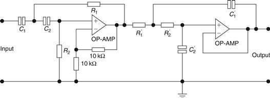
Figure 17.26 Bandpass filter
Example 17.12
Design a first-order bandpass filter which has a pass-band gain of 4, a lower cut-off frequency f1=200 Hz and an upper cut-off frequency of fh=1 kHz. Draw the frequency response of this filter.
Solution
As the gain has to be 4 overall then each filter should have a gain of 2. Hence, if the filter uses op-amps in the noninverting mode, then Ra and Rb are calculated by using:

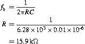
Let R1=10 kΩ. So both filter sections will have gain setting resistors of 10 kΩ. The values for both sections of the filter are calculated as follows. For the high-pass section,

Let C=0.05 μF. Then,
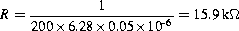
For the low-pass section,
The response for this filter is shown in Figure 17.27.
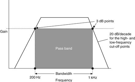
Figure 17.27 Response for filter of Example 17.12
Example 17.13
Design a filter which when cascaded with the high-pass filter in Figure 17.28 will give an overall bandwidth of 35 krad/s and an overall maximum gain of 17.17 at the center frequency. The response should be flat and the roll-off 40 dB/decade.
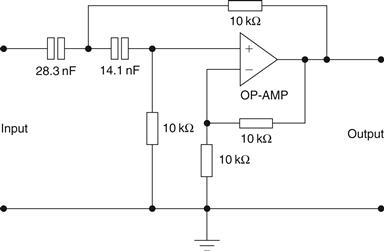
Figure 17.28 High-pass filter (Example 17.13)
Solution
For the high-pass filter in Figure 17.28, normalized values can be calculated by noting that R1/R2=1 and C1/C2=2. Hence, R1=R2=1 Ω, C1=1.414F and C2=0.707 F. So from the tables the pass-band gain is 2 for these normalized values. Also,
Hence a low-pass filter is required with a cut-off frequency of:

(this is the upper cut-off frequency). Since the maximum gain at the center frequency has to be 3.17=10 dB then the gain of the second filter is:

So the gain of the second filter has to be 1.585, and from the normalized tables for a low-pass Butterworth we have:

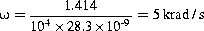
If a denormalization factor of 104 is used and ω=40 krad/s, then:

Finally,
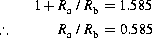
Select Ra=10 kΩ and Rb=17 kΩ. The complete filter is shown in Figure 17.29.
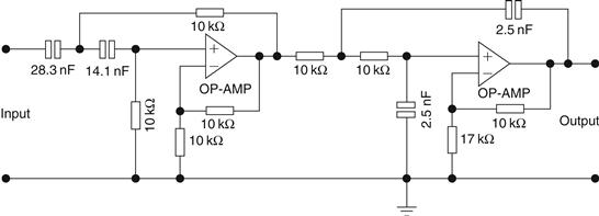
Figure 17.29 Complete filter for Example 17.13
Example 17.14
It is required to build a third-order low-pass filter with a cut-off frequency of 1 kHz and a pass-band gain of 2. Design such a filter.
Solution
A first-order and second-order filter can be connected in series to satisfy this circuit. In order to guarantee a Butterworth response the gain values of both circuits must be adhered to so for the first order a pass-band gain of 1 will be set, while the second order will have a pass-band gain of 2. The usual calculations are carried out using the normalized tables and the Butterworth low-pass normalized values. The full circuit is given in Figure 17.30.
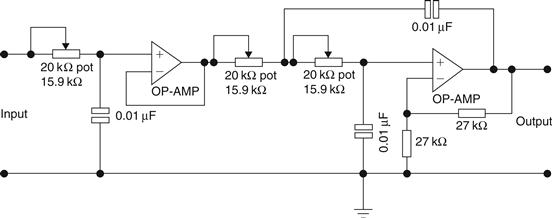
Figure 17.30 Circuit for Example 17.14
Leave a Reply