Current-carrying conductors range from the small wires of home circuits to massive bus bar sets that may carry several hundred kiloamperes. Copper is the primary conductor, with aluminum often used for bus bars and transformer windings. Conductor cross-sectional areas are designated by American Wire Gauge (AWG) number in the smaller sizes, with a decrease of three numbers representing a doubling of the cross-sectional area. Numbered sizes go up to #0000, 4Ø (four aught). For larger conductors, the cross sections are expressed directly in circular mils, D2, where D is the conductor diameter in thousandths of an inch. For example, a conductor 1/2 inch in diameter would be 250,000 circular mils. This would usually be expressed as 250 kcm, although older tables may use 250 mcm. For noncircular conductors, the area in circular mils is the area in square inches times (4/π)×106.
High-current conductors are usually divided into a number of spaced parallel bus bars to facilitate cooling. A rough guide to current capacity for usual conditions is 1000 A/in2 of cross section. Connections between bus bar sections should be designed to avoid problems from differential expansion between the conductors and the bolts that fasten them, as both heat up from current or ambient temperature. Silicon bronze bolts are a good match for the temperature coefficient of expansion of copper, and they have sufficient strength for good connections. However, highly reliable connections can be made between copper or aluminum bus sections with steel bolts and heavy Belleville washers on top of larger-diameter steel flat washers. The joint should be tightened until the Belleville washer is just flat. Ordinary split washers are not recommended. If the bus is subjected to high magnetic fields, stainless steel hardware should be used, but the field from the bus itself does not usually require this. Environmental conditions, however, may favor stainless.
All joints in buswork must be clean and free of grease. Joints can be cleaned with fine steel wool and coated with a commercial joint compound before bolting. Aluminum bus must be cleaned free of all oxide and then immediately protected with an aluminum-rated joint compound to prevent oxide formation.
Most control wiring is made with bare copper stranded conductors having 300- or 600-V insulation, much of which is polyvinyl chloride (PVC). These conductors are generally listed by Underwriter’s Laboratories, the Canadian Standards Association, or both. Most equipment standards require labeled wire that carries a UL or CSA printed listing number along with AWG gauge and insulation temperature rating (see Figure 15.2). The National Electric Code should be followed for the required current rating of the conductors. Power wiring is similar to control wiring except, of course, for being much larger. Cabinet wiring is often limited to about 250 kcm because of the necessary tight bending radii, although there are no hard rules on this.

Figure 15.2 Typical wire labeling
In sequence, these identify the vendor, appliance wire, wire size, voltage rating, fire retardant class, insulation temperature, Underwriter’s Laboratories as a listing agency, appliance wire listing number, CSA as a listing agency, alternate use as control circuit wire, maximum operating temperature, and listing identification.
Stranded conductors should be terminated in pressure-swaged crimp connectors that then can be bolted to bus work or terminal blocks. Circuit breakers and other power devices often have provisions for fastening stranded conductors with clamp plates or pressure bolts with rounded ends. Swaged connectors should not be used on these terminals. Fine-strand, extra-flexible welding cable should never be used with clamp plates. Pressure-crimped connectors are imperative.
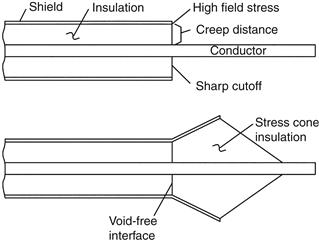
Medium-voltage conductors rated to 7.5 kV are available either shielded or unshielded, but higher-voltage cables must be shielded unless air spaced from other conductors and ground. Spacings must follow standards. Shielded conductors have a center current-carrying conductor, a layer of insulation, and then a conductive shield covered by an insulated protective layer. The shield is grounded. This arrangement assures that the radial electrostatic field is uniform along the length and that there are no voids in the insulation to cause corona deterioration. Terminations are made with stress cones, devices of several types that gradually increase the insulation radius to an extended shield while maintaining void-free conditions. When the radius is sufficient to reduce the voltage stress to allowable levels, the shield can be ended and conventional terminal lugs attached to the extended insulated conductor. Some stress cones have shrink-fit tubing and others a silicone grease to eliminate voids. Figure 15.3 shows a typical arrangement.

Figure 15.3 Stress cone termination for shielded cable
The forces between current-carrying conductors vary as the square of the current, so bracing for fault currents becomes a serious issue in high-power equipment. Electronic systems such as motor starters that are connected directly to a power line may face especially high fault currents. Circuit breakers require several cycles to trip and are of no use in limiting initial fault currents. Ordinary fuses also have relatively long melting times and do not help. On the other hand, semiconductor-type fuses will melt subcycle and limit fault current, the magnitude of which is a function of the prospective fault current without a fuse. The force in pounds per linear foot developed between two parallel round conductors with spacing d in inches is:

where I is the rms fault current in each. The force is dependent on the conductor geometry. Forces are attractive for currents in the same direction and repulsive for opposite polarities.
When equipment is supplied from an internal transformer rated for the load current, the steady-state fault current will seldom exceed twenty times rated current (1/Xpu). However, an inductive source causes an asymmetric fault current that theoretically may reach a maximum of twice the steady-state peak value. Although L/R current decay makes a peak of around 1.5 times steady-state peak more likely, this still allows more than twice the steady-state peak force, since the force is proportional to current squared. Circuit breakers are rated for a maximum peak current that will allow them to close and latch the mechanism.
High-current conductors are sometimes made with liquid cooling, one form utilizing copper tubing soldered or brazed into grooves that are milled into the edge of the bus. An advantage of liquid cooling in general is that most of the heat generated in the equipment can be transferred to the water, thus minimizing heating of the air in cabinets with power electronics. Liquid cooling also saves on copper.
Buswork carrying high levels of AC currents, especially with a high harmonic content, may cause parasitic heating of adjacent steel cabinet parts due to induced eddy currents. One solution to the problem is to replace the cabinet sections with stainless steel, aluminum, or fiberglass sheet and structural members. Another solution is to interpose a copper plate between the bus and the offending cabinet member. The plate will have high eddy currents, but the low resistance of the copper will minimize losses. Eddy currents in the copper will generate a flux in opposition to the incident flux to shield the cabinet steel.
Leave a Reply