
There are two basic types of control systems:
In an open-loop control system the output from the system has no effect on the input signal to the plant or process. The output is determined solely by the initial setting. Open-loop systems have the advantage of being relatively simple and consequently cheap with generally good reliability. However, they are often inaccurate since there is no correction for errors in the output which might result from extraneous disturbances.
As an illustration of an open-loop system, consider the heating of a room to some required temperature using an electric fire which has a selection switch which allows a 1 kW or a 2 kW heating element to be selected. The decision might be made, as a result of experience, that to obtain the required temperature it is only necessary to switch on the 1 kW element. The room will heat up and reach a temperature which is determined by the fact the 1 kW element is switched on. The temperature of the room is thus controlled by an initial decision and no further adjustments are made. Figure 18.6 illustrates this. If there are changes in the conditions, perhaps someone opening a window, no adjustments are made to the heat output from the fire to compensate for the change. There is no information fed back to the fire to adjust it and maintain a constant temperature.
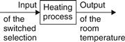
Figure 18.6 Open-loop system with no feedback of output to modify the input if there are any extraneous disturbances
Open-loop control is often used with processes that require the sequencing of events by on-off signals, like washing machines which require the water to be switched on and then, after a suitable time, switched off followed by the heater being switched on and then, after a suitable time, switched off.
In a closed-loop control system a signal indicating the state of the output of the system is fed back to the input where it is compared with what was required and the difference used to modify the output of the system so that it maintains the output at the required value (Figure 18.7). The term closed-loop refers to the loop created by the feedback path. Closed-loop systems have the advantage of being relatively accurate in matching the actual to the required values. They are, however, more complex and so more costly with a greater chance of breakdown as a consequence of the greater number of components.
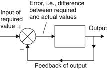
Figure 18.7 Closed-loop system with feedback of output to modify the input and so adjust for any extraneous disturbances
As an illustration, consider modifications of the open-loop heating system described above to give a closed-loop system. To obtain the required temperature, a person stands in the room with a thermometer and switches the 1 kW and 2 kW elements on or off, according to the difference between the actual room temperature and the required temperature in order to maintain the temperature of the room at the required temperature. In this situation there is feedback, information being fed back from the output to modify the input to the system. Thus if a window is opened and there is a sudden cold blast of air, the feedback signal changes because the room temperature changes and is fed back to modify the input to the system. The input to the heating process depends on the deviation of the actual temperature fed back from the output of the system from the required temperature initially set. Figure 18.8 illustrates this system with the comparison element represented by the summing symbol with a + opposite the set value input and a – opposite the feedback signal to give the sum as + set value – feedback value = error. This error signal is then used to control the process. Because the feedback signal is subtracted from the set value signal, the system is said to have negative feedback.
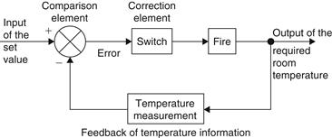
Figure 18.8 Closed-loop system with feedback being used to modify the input to the controller and so enable the control system to adjust when there are extraneous disturbances
18.3.1 Basic Elements of an Open-Loop Control System
The term open-loop control system is used for a system where an input to a system is chosen on the basis of previous experience as likely to give the output required. Figure 18.9 shows the basic form of such a system.
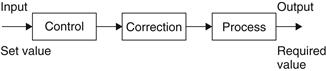
Figure 18.9 Basic elements of an open-loop control system
The system has three basic elements: control, correction and the process of which a variable is being controlled.
This determines the action to be taken as a result of the input to the system.
This has an input from the controller and gives an output of some action designed to change the variable being controlled.
This is the process of which a variable is being controlled.
There is no changing of the control action to account for any disturbances which change the output variable.
18.3.2 Basic Elements of a Closed-Loop System
Figure 18.10 shows the general form of a basic closed-loop system.
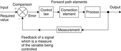
Figure 18.10 Basic elements of a closed-loop control system
The following are the functions of the constituent elements:
This element compares the required value of the variable being controlled with the measured value of what is being achieved and produces an error signal:

Thus if the output is the required value then there is no error and so no signal is fed to initiate control. Only when there is a difference between the required value and the actual values of the variable will there be an error signal and so control action initiated.
2. Control law implementation element
The control law element determines what action to take when an error signal is received. The control law used by the element may be just to supply a signal which switches on or off when there is an error, as in a room thermostat, or perhaps a signal which is proportional to the size of the error. With a proportional control law implementation, if the error is small a small control signal is produced and if the error is large a large control signal is produced. Other control laws include integral mode where a control signal is produced that continues to increase as long as there is an error and derivative mode where the control signal is proportional to the rate at which the error is changing.
The term control unit or controller is often used for the combination of the comparison element, i.e., the error detector, and the control law implementation element. An example of such an element is a differential amplifier which has two inputs, one the set value and one the feedback signal, and any difference between the two is amplified to give the error signal. When there is no difference there is no resulting error signal.
The correction element or, as it is often called, the final control element, produces a change in the process which aims to correct or change the controlled condition. The term actuator is used for the element of a correction unit that provides the power to carry out the control action. An example is a motor, with an input of a voltage to its armature coils and an output of a rotating shaft which, via possibly a screw, rotates and corrects the position of a workpiece (Figure 18.11(a)). Another example is a hydraulic or pneumatic cylinder (Figure 18.11(b)). The cylinder has a piston which can be moved along the cylinder depending on a pressure signal from the controller.
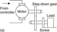
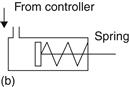
Figure 18.11 Actuator examples: (a) motor; (b) cylinder
The process is the system in which there is a variable that is being controlled; for example, it might be a room in a house with its temperature being controlled.
The measurement element produces a signal related to the variable condition of the process that is being controlled. For example, it might be a temperature sensor with suitable signal processing.
The following are terms used to describe the various paths through the system taken by signals:
Feedback is a means whereby a signal related to the actual condition being achieved is fed back to modify the input signal to a process. The feedback is said to be negative when the signal which is fed back subtracts from the input value. It is negative feedback that is required to control a system. Positive feedback occurs when the signal fed back adds to the input signal.
The term forward path is used for the path from the error signal to the output. In Figure 18.10 these forward path elements are the control law element, the correction element and the process element.
18.3.3 Discrete Event Control
This is often described as sequential control and describes control systems where control actions are determined in response to observed time-critical events. For example, the filling of a container with water might have a sensor at the bottom that registers when the container is empty and so gives an input to the controller to switch the water flow on and a sensor at the top that registers when the container is full and so gives an input to the controller to switch off the flow of water. This is a form of closed-loop system since the controller is receiving feedback from the two sensors regarding the state of the variable (Figure 18.12).
Figure 18.12 Discrete-event control with the controller switching the valve open when empty signal received and closed when the full signal
Leave a Reply