
The following are examples of correction elements that are commonly encountered in control systems.
18.6.1 Directional Control Valves
A directional control valve on the receipt of some external signal, which might be mechanical, electrical or a pressure signal, change the direction of, or stop, or start the flow of fluid in some part of the pneumatic/ hydraulic circuit. Thus, it might be used to control the direction of fluid flow to a cylinder and so use the movement of its piston to carry out actuation.
The basic symbol for a control valve is a square. With a directional control valve two or more squares are used, with each square representing the positions to which the valve can be switched. Thus, Figure 18.45(a) represents a valve with two switching positions, Figure 18.45(b) a valve with three switching positions. Lines in the boxes are used to show the flow paths with arrows indicating the direction of flow (Figure 18.46(a)) and shut-off positions indicated by terminated lines (Figure 18.46(b)). The pipe connections, i.e., the inlet and outlet ports of the valve, are indicated by lines drawn on the outside of the box and are drawn for just the “rest/initial/neutral position,” i.e., when the valve is not actuated (Figure 18.46(c)). You can imagine each of the position boxes to be moved by the action of some actuator so that it connects up with the pipe positions to give the different connections between the ports. Directional control valves are described by the number of ports and the number of positions. Thus, a 2/2 valve has 2 ports and 2 positions, a 3/2 valve 3 ports and 2 positions, a 4/2 valve 4 ports and 2 positions, a 5/3 valve 5 ports and 3 positions. Figure 18.47 shows some commonly used examples and their switching options and Figure 18.48 the means by which valves can be switched between positions.

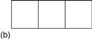
Figure 18.45 (a) Two position; (b) three position valves


Figure 18.46 (a) Flow path; (b) shut-off; (c) initial connections
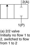
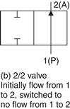
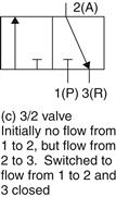
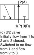
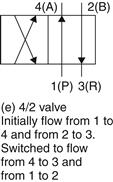
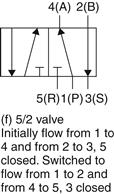
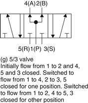
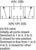
Figure 18.47 Commonly used direction valves: P or I indicates the pressure supply ports, R and S or 3 and 5 the exhaust ports, A and B or 2 and 4 the signal output ports
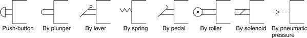
Figure 18.48 Examples of valve actuation methods
As an illustration, Figure 18.49 shows the symbol for a 3/2 valve with solenoid activation and return by means of a spring. Thus, when the solenoid is not activated by a current through it, the signal port 2 is connected to the exhaust 3 and so is at atmospheric pressure. When the solenoid is activated, the pressure supply P is connected to the signal port 2 and thus the output is pressurised.
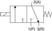
Figure 18.49 Symbol for a solenoid-activated valve with return spring
Figure 18.50 shows how such a valve might be used to cause the piston in a single-acting cylinder to move; the term single-acting is used when a pressure signal is applied to only one side of the piston. When the switch is closed and a current passes through the solenoid, the valve switches position and pressure is applied to extend the piston in the cylinder.
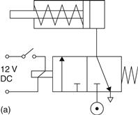
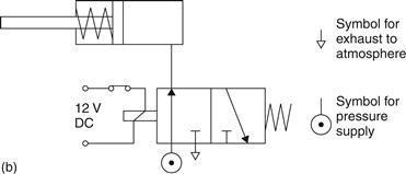
Figure 18.50 Control of a single-acting cylinder: (a) before solenoid activated; (b) when solenoid activated
Figure 18.51 shows how a double-solenoid activated valve can be used to control a double-acting cylinder. Momentary closing switch S1 causes a current to flow through the solenoid at the left-hand end of the valve and so result in the piston extending. On opening S1 the valve remains in this extended position until a signal is received by the closure of switch S2 to activate the fight-hand solenoid and return the piston.
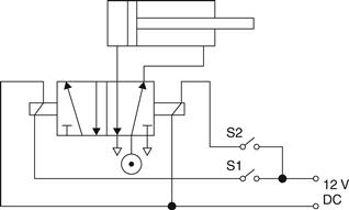
Figure 18.51 Control of a double-acting cylinder
18.6.2 Flow Control Valves
In many control systems the rate of flow of a fluid along a pipe is controlled by a valve which uses pneumatic action to move the valve stem and hence a plug in the flow path (Figure 18.52), so altering the size of the gap through which the fluid can flow. The movement of the stem results from the use of a diaphragm moving against a spring and controlled by air pressure (Figure 18.53). The air pressure from the controller exerts a force on one side of the diaphragm, the other side of the diaphragm being at atmospheric pressure, which is opposed by the force due to the spring on the other side. When the air pressure changes then the diaphragm moves until there is equilibrium between the forces resulting from the pressure and those from the spring. Thus the pressure signals from the controller result in the movement of the stem of the valve. The difference between the direct and reverse forms in Figure 18.53 is the position of the spring.
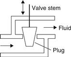
Figure 18.52 Flow controlled by movement of a plug
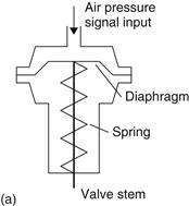
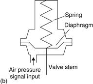
Figure 18.53 (a) Direct action; (b) reverse action
There are many forms of valve body and plug. The selection of the form of body and plug determine the characteristic of the control valve, i.e., the relationship between the valve stem position and the flow rate through it. For example, Figure 18.54 shows how the selection of plug can be used to determine whether the valve closes when the controller air pressure increases or opens when it increases and Figure 18.55 shows how the shape of the plug determines how the rate of flow is related to the displacement of the valve stem: linear plug—change in flow rate proportional to the change in valve stem displacement; quick-opening plug—a large change in flow rate occurs for a small movement of the valve stem; equal percentage plug—the amount by which the flow rate changes is proportional to the value of the flow rate when the change occurs.
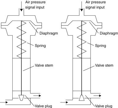
Figure 18.54 Direct action: (a) air pressure increase to close; (b) air pressure increase to open
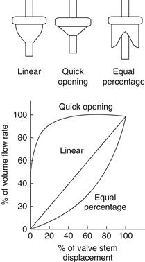
Figure 18.55 Effect of plug shape on flow
18.6.3 DC Motors
DC motors are widely used with control systems. In the DC motor, coils of wire are mounted in slots on a cylinder of magnetic material called the armature. The armature is mounted on beatings and is free to rotate. It is mounted in the magnetic field produced by field poles. This magnetic field might be produced by permanent magnets or an electromagnet with its magnetism produced by a current passing through the, so-termed, field coils. Whether permanent magnet or electromagnet, these generally form the outer casing of the motor and are termed the stator.
For a DC motor with the field provided by a permanent magnet, the direction of rotation of the motor can be changed by reversing the current in the armature coil. The speed of rotation of such a motor can be changed by changing the size of the current to the armature coil.
DC motors with field coils are classified as series, shunt, compound and separately excited according to how the field windings and armature windings are connected. With the series-wound motor the armature and fields coils are in series (Figure 18.56(a)). Such a motor exerts the highest starting torque and has the greatest no-load speed. However, with light loads there is a danger that a series-wound motor might run at too high a speed. Reversing the polarity of the supply to the coils has no effect on the direction of rotation of the motor, since both the current in the armature and the field coils are reversed. With the shunt-wound motor (Figure 18.56(b)) the armature and field coils are in parallel. It provides the lowest starting torque, a much lower no-load speed and has good speed regulation. It gives almost constant speed regardless of load and thus shunt wound motors are very widely used. To reverse the direction of rotation, either the armature or field current can be reversed. The compound motor (Figure 18.56(c)) has two field windings, one in series with the armature and one in parallel. Compound-wound motors aim to get the best features of the series and shunt-wound motors, namely a high starting torque and good speed regulation. The separately excited motor (Figure 18.56(d)) has separate control of the armature and field currents. The direction of rotation of the motor can be obtained by reversing either the armature or the field current. Figure 18.57 indicates the general form of the torque-speed characteristics of the above motors. The separately excited motor has a torque-speed characteristic similar to the shunt wound motor. The speed of such DC motors can be changed by either changing the armature current or the field current. Generally it is the armature current that is varied.
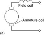
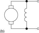
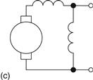
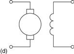
Figure 18.56 (a) Series; (b) shunt; (c) compound;(d) separately wound
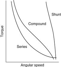
Figure 18.57 Torque-speed characteristics of DC motors
The choice of DC motor will depend on what it is to be used for. Thus, for example, with a robot manipulator the robot wrist might use a series-wound motor because the speed decreases as the load increases. A shunt-wound motor might be used if a constant speed was required, regardless of the load.
18.6.4 Stepper Motor
The stepper or stepping motor produces rotation through equal angles, the so-called steps, for each digital pulse supplied to its input. For example, if with such a motor 1 input pulse produces a rotation of 1.8° then 20 input pulses will produce a rotation through 36.0°, 200 input pulses a rotation through one complete revolution of 360°. It can thus be used for accurate angular positioning. By using the motor to drive a continuous belt, the angular rotation of the motor is transformed into linear motion of the belt and so accurate linear positioning can be achieved. Such a motor is used with computer printers, x-y plotters, robots, machine tools and a wide variety of instruments for accurate positioning.
There are two basic forms of stepper motor, the permanent magnet type with a permanent magnet rotor and the variable reluctance type with a soft steel rotor. Both form of stepper motor have a stator with a number of diametrically opposite pairs of poles, each wound with a coil. Figure 18.58 shows the permanent magnet type with two pairs of stator poles. Each pole is activated by a current being passed through the appropriate field winding, the coils being such that opposite poles are produced on opposite coils. The current is supplied from a DC source to the windings through switches. With the currents switched through the coils such that the poles are as shown in Figure 18.58, the rotor will move to line up with the next pair of poles and stop there. This would be, for Figure 18.58, an angle of 45°. If the current is then switched so that the polarities are reversed, the rotor will move a step to line up with the next pair of poles, at angle 135° and stop there. The polarities associated with each step are given in Table 18.2.
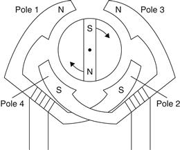
Figure 18.58 The basic principles of the permanent magnet stepper motor (2-phase) with a rotor giving
Table 18.2
Polarities associated with each step
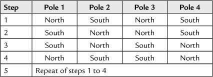
There are thus, in this case, four possible rotor positions: 45°, 135°, 225° and 315°. Note that the term phase is used for the number of independent windings on the stator.
Figure 18.59 shows the basic form of the variable reluctance type of stepper motor. With this form the rotor is made of soft steel and is not a permanent magnet. The rotor has a number of teeth, the number being less than the number of poles on the stator. When an opposite pair of windings on stator poles has current switched to them, a magnetic field is produced with lines of force which pass from the stator poles through the nearest set of teeth on the rotor. Since lines of force can be considered to be rather like elastic thread and always trying to shorten themselves, the rotor will move until the rotor teeth and stator poles line up. This is termed the position of minimum reluctance. Thus by switching the current to successive pairs of stator poles, the rotor can be made to rotate in steps. With the number of poles and rotor teeth shown in Figure 18.59, the angle between each successive step will be 30°. The angle can be made smaller by increasing the number of teeth on the rotor.
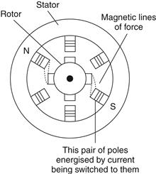
Figure 18.59 Basic principles of a 3-phase variable reluctance stepper motor
To drive a stepper motor, so that it proceeds step-by-step to provide rotation, requires each pair of stator coils to be switched on and off in the required sequence when the input is a sequence of pulses. Driver circuits are available to give the correct sequencing and Figure 18.60 shows an example. The stepper motor will rotate through one step each time the trigger input goes from low to high. The motor runs clockwie when the rotation input is low and anticlockwise when high. When the set pin is made low the output resets. In a control system, these input pulses might be supplied by a microprocessor.
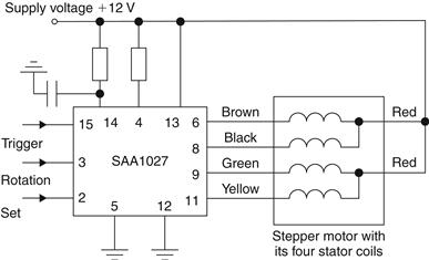
Figure 18.60 Driver circuit SAA 1027 for a 12 V 4-phase stepper motor
Leave a Reply