
Low- and high-pass first-order filters may be designed very easily if certain steps are followed:
1. The cut-off frequency must be known.
2. A value of C less than 1 μF (say) should be chosen.
3. Then calculate the value of R from equation (17.4) or (17.6), depending on the filter being designed.
4. Determine a value of A and calculate Rf and R1.
Example 17.1
Design a low-pass filter at a cut-off frequency of 2.4 kHz with a pass-band gain of 3.
Solution
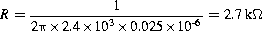
Select a value of C=0.025 μF. This will give:
Since the pass-band gain is 3 then:

Hence, Rf=2Ri and so various values are possible. If an unusual value is calculated then a potentiometer may be used to set the values. It should also be mentioned at this point that with advanced semiconductor technology a selection of very low values of capacitance in the nanofarad range is available from many manufacturers in chip form.
In order to complete the exercise the practical circuit is shown in Figure 17.13 and this can now be set up on a printed circuit board.
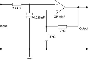
Figure 17.13 Circuit for Example 17.1
Example 17.2
Design a high-pass filter at a cut-off frequency of 1 kHz with a passband gain of 2.
Solution
Once again select a suitable value of C, such as 0.01 μF. Hence, since the cut-off frequency is 1 kHz, R=15.9 kΩ. Since A=2, the two feedback resistors are equal. Several solutions are possible, such as 10 kΩ.
Leave a Reply