
The first-order filter is the simplest type and forms the basis of all other filters. Normally, what is called the Butterworth type is analyzed. We will look at the low-pass filter first, a circuit for which is shown in Figure 17.9.
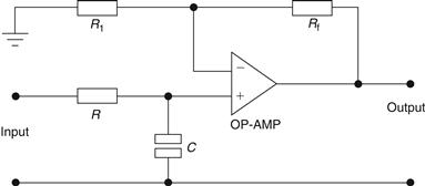
Figure 17.9 Low-pass Butterworth filter
In this circuit note that the op-amp is ideal, i.e., it draws no current, and also it is used in the noninverting mode in order to prevent loading down of the RC network. R and C act as a voltage-dividing network, and hence we have that:
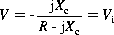
Simplifying this expression gives:

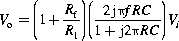
The output voltage is given as:

Hence,
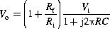
![]() (17.3)
(17.3)
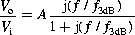
Note that;
![]() (17.4)
(17.4)
This has the characteristics of a first-order low-pass filter. When ω=0 then the pass-band gain is:
![]() (17.5)
(17.5)
This is simply the amplifier gain. Note also that when:

the gain has dropped by 3 dB after which the gain falls off at the rate of 20 dB/decade. A typical response for this filter is shown in Figure 17.10.
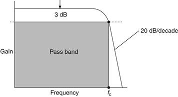
Figure 17.10 Typical filter response for low-pass
A similar analysis may be carried out for the first-order high-pass filter, which is shown in Figure 17.11. Note that these two filters are identical except that R and C have been interchanged. The output voltage is given by:
or,
Note that:
![]() (17.6)
(17.6)
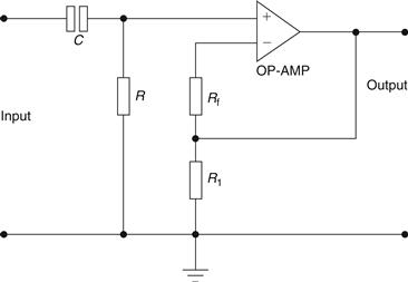
Figure 17.11 First-order high-pass filter
The response for this filter is shown below in Figure 17.12.
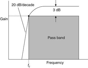
Figure 17.12 Response for high-pass filter
Leave a Reply