
This section briefly reviews some of the newer data interface standards that have grown up for high-speed purposes around particular applications and have subsequently become more widely entrenched.
13.4.1 EIA-485
EIA-485 shares many similarities with EIA-422, and is widely used as the basis for in-house and industrial datacom systems. For instance, one variant of the SCSI interface (HVD-SCSI: high voltage differential—small computer systems interface) uses 485 as the basis for its electrical specification. 485-compliant devices can be used in 422 systems, though the reverse is not necessarily true. The principal difference is that 485 allows multiple transmitters on the same line, driving up to 32 unit loads, with half-duplex (bidirectional) communication. One Unit Load is defined as a steady-state load allowing 1 mA of current under a maximum common mode voltage of 12 V or 0.8 mA at –7 V. ULs may consist of drivers or receivers and failsafe resistors (see below), but do not include the termination resistors. The bidirectional communication means that 485 drivers must allow for line contention and for driving a line that is terminated at each end with 120 W. The two specifications are compared in Table 13.2.
One further problem that arises in a half-duplex system is that there will be periods when no transmitters are driving the line, so that it becomes high impedance, and it is desirable for the receivers to remain in a fixed state in this situation. This means that a differential voltage of more than 200 mV should be provided by a suitable passive circuit that complies with both the termination impedance requirements and the unit load constraints. A network designed to do this is called a “failsafe” network.
13.4.2 CAN
The Controller Area Network standard was originally developed within the automotive industry to replace the complex electrical wiring harness with a two-wire data bus. It has since been standardized in ISO 11898. The specification allows signaling rates up to 1 MB/s, high immunity from electrical interference, and an ability to self-diagnose and repair errors. It is now widespread in many sectors, including factory automation, medical, marine, aerospace and of course automotive. It is particularly suited to applications requiring many short messages in a short period of time with high reliability in noisy operating environments.
The ISO 11898 architecture defines the lowest two layers of the OSI/ISO seven layer model, that is, the data-link layer and the physical layer. The communication protocol is carrier-sense multiple access, with collision detection and arbitration on message priority (CSMA/CD+AMP). The first version of CAN was defined in ISO 11519 and allowed applications up to 125 kB/s with an 11-bit message identifier. The 1 MB/s ISO 11898:1993 version is standard CAN 2.0 A, also with an 11-bit identifier, while Extended CAN 2.0B is provided in a 1995 amendment to the standard and provides a 29-bit identifier.
The physical CAN bus is a single twisted pair, shielded or unshielded, terminated at each end with 120 W. Balanced differential signaling is used. Nodes may be added or removed at any time, even while the network is operating. Unpowered nodes should not disturb the bus, so transceivers should be configured so that their pins are in a high impedance state with the power off. The standard specification allows a maximum cable length of 40 m with up to 30 nodes, and a maximum stub length (from the bus to the node) of 0.3 m. Longer stub and line lengths can be implemented, with a tradeoff in signaling rates. The recessive (quiescent) state is for both bus lines to be biased equally to approximately 2.5 V relative to ground; in the dominant state, one line (CANH) is taken positive by 1 V while the other (CANL) is taken negative by the same amount, giving a 2 V differential signal. The required common mode voltage range is from –2 V to +7 V, i.e., ±4.5 V about the quiescent state.
13.4.3 USB
The Universal Serial Bus is a cable bus that supports data exchange between a host computer and a wide range of simultaneously accessible peripherals. The attached peripherals share USB bandwidth through a host scheduled, token-based protocol. The bus allows peripherals to be attached, configured, used, and detached while the host and other peripherals are in operation. There is only one host in any USB system. The USB interface to the host computer system is referred to as the Host Controller, which may be implemented in a combination of hardware, firmware, or software.
USB devices are either hubs, which act as wiring concentrators and provide additional attachment points to the bus, or system functions such as mice, storage devices or data sources or outputs. A root hub is integrated within the host system to provide one or more attachment points.
The USB transfers signal and power over a four-wire point-to-point cable. A differential input receiver must be used to accept the USB data signal. The receiver has an input sensitivity of at least 200 mV when both differential data inputs are within the common mode range of 0.8 V to 2.5 V. A differential output driver drives the USB data signal with a static output swing in its low state of <0.3 V with a 1.5 kW load to 3.6 V and in its high state of >2.8 V with a 15 kW load to ground. A full-speed USB connection is made through a shielded, twisted pair cable with a characteristic impedance (Z0) of 90 W 15% and a maximum one-way delay of 26 ns. The impedance of each of the drivers must be between 28 and 44 W. The detailed specification controls the rise and fall times of the output drivers for a range of load capacitances.
In version 1.1, there are two data rates:
• the full-speed signaling bit rate is 12 Mb/s;
• a limited capability low-speed signaling mode is also defined at 1.5 Mb/s.
Both modes can be supported in the same USB bus by automatic dynamic mode switching between transfers. The low-speed mode is defined to support a limited number of low-bandwidth devices, such as mice. In order to provide guaranteed input voltage levels and proper termination impedance, biased terminations are used at each end of the cable. The terminations also allow detection of attachment at each port and differentiate between full-speed and low-speed devices. The USB 2.0 specification adds a high-speed data rate of 480 MB/s between compliant devices using the same cable as 1.1, with both source and load terminations of 45 W.
The cable also carries supply wires, nominally +5 V, on each segment to deliver power to devices. Cable segments of variable lengths, up to several meters, are possible. The specification defines connectors, and the cable has four conductors: a twisted signal pair of standard gauge and a power pair in a range of permitted gauges.
The clock is transmitted, encoded along with the differential data. The clock encoding scheme is non-return-to-zero with bit stuffing to ensure adequate transitions. A SYNC field precedes each packet to allow the receiver(s) to synchronize their bit recovery clocks.
13.4.4 Ethernet
Ethernet is a well established specification for serial data transmission. It was first published in 1980 by a multivendor consortium that created the DEC-Intel-Xerox (DIX) standard. In 1985 Ethernet was standardized in IEEE 802.3, since when it has been extended a number of times. “Classic” Ethernet operates at a data transmission rate of 10 Mbit/s. Since the 1990s, Ethernet has developed in the following areas:
– Fast Ethernet at 100 Mbit/s (1995)
– Gigabit Ethernet at 1 Gbit/s (1999)
Nowadays Ethernet is the most widespread networking technology in the world in commercial information technology systems, and is also gaining importance in industrial automation. All network users have the same rights under Ethernet. Any user can exchange data of any size with another user at any time, and any network device that is transmitting is heard by all other users. Each Ethernet user filters the data packets that are intended for it out from the stream, ignoring all the others.
In the standard Ethernet, all the network users share one collision domain. Network access is controlled by the CSMA/CD procedure (Carrier Sense Multiple Access with Collision Detection). Before transmitting data, a network user first checks whether the network is free (carrier sense). If so, it starts to transmit data. At the same time it checks whether other users have also begun to transmit (collision detection). If that is the case, a collision occurs. All the network users concerned now stop their transmission, wait for a period of time determined according to a randomizing principle, and then start transmission again. The result of this is that the time required to transmit data packets depends heavily on the network loading, and cannot be determined in advance. The more collisions occur, the slower the entire network becomes.
This lack of determinism can be overcome by a variant of the basic approach known as switched Ethernet. This refers to a network in which each Ethernet user is assigned a port in a switch, which analyses all the data packets as they arrive, directing them on to the appropriate port. Switches separate former collision domains into individual point-to-point connections between the network components and the relevant user equipment. Preventing collisions makes the full network bandwidth available to each point-to-point connection. The second pair of conductors in the four-wire Ethernet cable, which otherwise is needed for collision detection, can now be used for transmission, so providing a significant increase in data transfer rate.
The Ethernet interface at each user is defined according to Figure 13.8. It is usual to find structured twisted pair local area network wiring already integrated within a building, and the cabling characteristics are given in IEC 11801 and related standards; hence, the 10Base-T and 100Base-T variants are the most popular of the Ethernet implementations, and the appropriate MAU/MDI using the RJ45 connector are included in most types of computer. The maximum lengths are set by signal timing limitations in the Fast Ethernet implementation, and an Ethernet system implementation relies on correct integration of cable lengths, types and terminations.
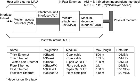
Figure 13.8 Ethernet interface and media
In contrast to the coaxial versions of Ethernet, which may be connected in multidrop, each segment of twisted pair or fiber route is a point-to-point connection between hosts; this means that a network system that is more than simply two hosts requires a number of hubs or switches, which integrate the connections to each user. A hub will simply pass through the Ethernet traffic between its ports without controlling it in any way, but a switch does control the traffic, separating packets to their destination ports.
The 100Base-T electrical characteristics are a peak differential output signal of 1 V into a 100 W characteristic impedance twisted pair; the 10Base-T level is 2.5 V. The rise and fall time and amplitude symmetries are also defined to achieve a high level of balance and hence common mode performance. It is normal to use a transformer and common mode choke to isolate the network connection from the driver electronics.
Leave a Reply