A complex number is of the form (a+jb) where a is a real number and jb is an imaginary number. Therefore, (1+j2) and (5 –j7) are examples of complex numbers.
By definition, ![]() and j2=–1
and j2=–1
(Note: In electrical engineering, the letter j is used to represent ![]() instead of the letter i, as commonly used in pure mathematics, because i is reserved for current.)
instead of the letter i, as commonly used in pure mathematics, because i is reserved for current.)
Complex numbers are widely used in the analysis of series, parallel and series-parallel electrical networks supplied by alternating voltages, in deriving balance equations with AC bridges, in analyzing AC circuits using Kirchhoff’s laws, mesh and nodal analysis, the superposition theorem, with Thévenin’s and Norton’s theorems, and with delta-star and star-delta transforms, and in many other aspects of higher electrical engineering. The advantage of the use of complex numbers is that the manipulative processes become simply algebraic processes.
A complex number can be represented pictorially on an Argand diagram. In Figure 7.1, the line 0 A represents the complex number (2+j3), 0B represents (3 –j), 0C represents (–2+j2) and 0D represents (–4 –j3).
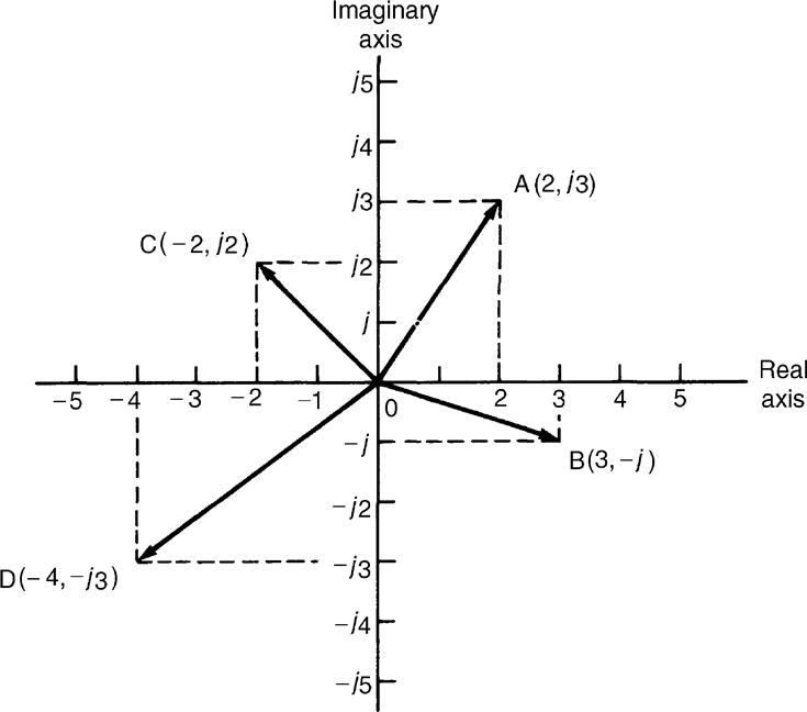
Figure 7.1 The Argand diagram
A complex number of the form a+jb is called a Cartesian or rectangular complex number. The significance of the j operator is shown in Figure 7.2. In Figure 7.2(a) the number 4 (i.e., 4+j0) is shown drawn as a phasor horizontally to the right of the origin on the real axis. (Such a phasor could represent, for example, an alternating current, i=4 sin ωt amperes, when time t is zero.)
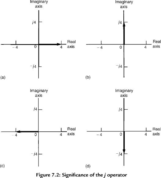
Figure 7.2 Significance of the j operator
The number j4 (that is, 0+j4) is shown in Figure 7.2(b) drawn vertically upwards from the origin on the imaginary axis. Multiplying the number 4 by the operator j results in an anticlockwise phase-shift of 90° without altering its magnitude.
Multiplying j4 by j gives j24, i.e., –4, and is shown in Figure 7.2(c) as a phasor four units long on the horizontal real axis to the left of the origin—an anticlockwise phase-shift of 90 compared with the position shown in Figure 7.2(b). Thus, multiplying by j2 reverses the original direction of a phasor.
Multiplying j24 by j gives j34, i.e., –j4, and is shown in Figure 7.2(d) as a phasor four units long on the vertical, imaginary axis downward from the origin—an anticlockwise phase-shift of 90 compared with the position shown in Figure 7.2(c).
Multiplying j34 by j gives j44, i.e., 4, which is the original position of the phasor shown in Figure 7.2(a).
Summarizing, application of the operator j to any number rotates it 90° anticlockwise on the Argand diagram, multiplying a number by j2 rotates it 180° anticlockwise, multiplying a number by j3 rotates it 270° anticlockwise and multiplication by j4 rotates it 360° anticlockwise, i.e., back to its original position. In each case, the phasor is unchanged in its magnitude.
By similar reasoning, if a phasor is operated on by –j then a phase shift of –90° (i.e., clockwise direction) occurs, again without change of magnitude.
In electrical circuits, 90° phase shifts occur between voltage and current with pure capacitors and inductors; this is the key as to why j notation is used so much in the analysis of electrical networks. This is explained later in this chapter.
Leave a Reply