
As well as their application as a general-purpose amplifying device, operational amplifiers have a number of other uses, including voltage followers, differentiators, integrators, comparators, and summing amplifiers. We shall conclude this section by taking a brief look at each of these applications.
11.9.1 Voltage Followers
A voltage follower using an operational amplifier is shown in Figure 11.11. This circuit is essentially an inverting amplifier in which 100% of the output is fed back to the input. The result is an amplifier that has a voltage gain of 1 (i.e., unity), a very high input resistance and a very high output resistance. This stage is often referred to as a buffer and is used for matching a high-impedance circuit to a low-impedance circuit.
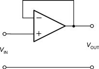
Figure 11.11 A voltage follower
Typical input and output waveforms for a voltage follower are shown in Figure 11.12. Notice how the input and output waveforms are both in-phase (they rise and fall together) and that they are identical in amplitude.
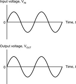
Figure 11.12 Typical input and output waveforms for a voltage follower
11.9.2 Differentiators
A differentiator using an operational amplifier is shown in Figure 11.13. A differentiator produces an output voltage that is equivalent to the rate of change of its input. This may sound a little complex but it simply means that, if the input voltage remains constant (i.e., if it isn’t changing) the output also remains constant. The faster the input voltage changes the greater will the output be. In mathematics this is equivalent to the differential function.
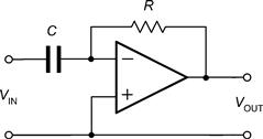
Figure 11.13 A differentiator
Typical input and output waveforms for a differentiator are shown in Figure 11.14. Notice how the square wave input is converted to a train of short duration pulses at the output. Note also that the output waveform is inverted because the signal has been applied to the inverting input of the operational amplifier.
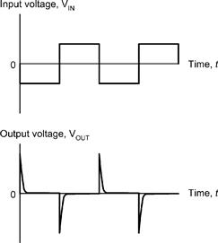
Figure 11.14 Typical input and output waveforms for a differentiator
11.9.3 Integrators
An integrator using an operational amplifier is shown in Figure 11.15. This circuit provides the opposite function to that of a differentiator (see earlier) in that its output is equivalent to the area under the graph of the input function rather than its rate of change. If the input voltage remains constant (and is other than 0 V) the output voltage will ramp up or down according to the polarity of the input. The longer the input voltage remains at a particular value the larger the value of output voltage (of either polarity) will be produced.
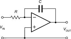
Figure 11.15 An integrator
Typical input and output waveforms for an integrator are shown in Figure 11.16. Notice how the square wave input is converted to a wave that has a triangular shape. Once again, note that the output waveform is inverted.
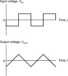
Figure 11.16 Typical input and output waveforms for an integrator
11.9.4 Comparators
A comparator using an operational amplifier is shown in Figure 11.17. Since no negative feedback has been applied, this circuit uses the maximum gain of the operational amplifier. The output voltage produced by the operational amplifier will thus rise to the maximum possible value (equal to the positive supply rail voltage) whenever the voltage present at the non-inverting input exceeds that present at the inverting input. Conversely, the output voltage produced by the operational amplifier will fall to the minimum possible value (equal to the negative supply rail voltage) whenever the voltage present at the inverting input exceeds that present at the non-inverting input.
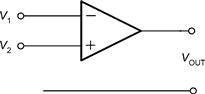
Figure 11.17 A comparator
Typical input and output waveforms for a comparator are shown in Figure 11.18. Notice how the output is either +15 V or -15 V depending on the relative polarity of the two input. A typical application for a comparator is that of comparing a signal voltage with a reference voltage. The output will go high (or low) in order to signal the result of the comparison.
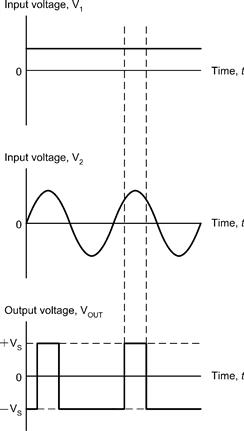
Figure 11.18 Typical input and output waveforms for a comparator
11.9.5 Summing Amplifiers
A summing amplifier using an operational amplifier is shown in Figure 11.19. This circuit produces an output that is the sum of its two input voltages. However, since the operational amplifier is connected in inverting mode, the output voltage is given by:

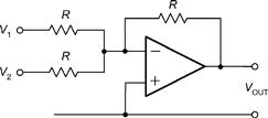
Figure 11.19 A summing amplifier
where V1 and V2 are the input voltages (note that all of the resistors used in the circuit have the same value). Typical input and output waveforms for a summing amplifier are shown in Figure 11.20. A typical application is that of “mixing” two input signals to produce an output voltage that is the sum of the two.
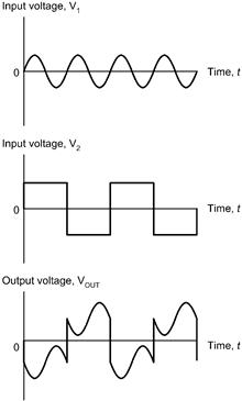
Figure 11.20 Typical input and output waveforms for a summing amplifier
Leave a Reply