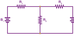
shows three resistors, R1, R2 and R3 connected across each other, i.e., in parallel, across a battery source of V volts.
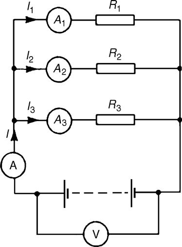
Figure 3.9 : Parallel resistors
In a parallel circuit:
(a) the sum of the currents I1, I2 and I3 is equal to the total circuit current, I, i.e., I =I1 +I2 +I3, and
(b) the source voltage, V volts, is the same across each of the resistors.
From Ohm’s law:
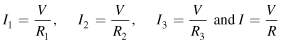
where R is the total circuit resistance.
Since I =I1 +I2 +I3
then ![]()
Dividing throughout by V gives:
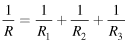
This equation must be used when finding the total resistance R of a parallel circuit. For the special case of two resistors in parallel:
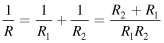
Hence, ![]()
Example 3.6
For the circuit shown in Figure 3.10, determine (a) the reading on the ammeter, and (b) the value of resistor R2.
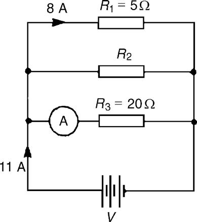
Figure 3.10 : Circuit for Example 3.6
Solution
Voltage across R1 is the same as the supply voltage V. Hence, supply voltage V = 8×5=40 V.
(b) Current flowing through R2 = 11-8-2=1 A
Hence, ![]()
Example 3.7
Two resistors, of resistance 3 Ω and 6 Ω, are connected in parallel across a battery having a voltage of 12 V. Determine (a) the total circuit resistance and (b) the current flowing in the 3 Ω resistor.
Solution
The circuit diagram is shown in Figure 3.11.
(a) The total circuit resistance R is given by:
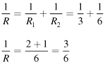
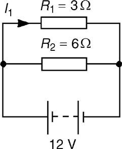
Figure 3.11 : Circuit for Example 3.7
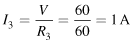
(b) Current in the 3 Ω resistance, ![]()
Example 3.8
For the circuit shown in Figure 3.12, find (a) the value of the supply voltage V and (b) the value of current I.
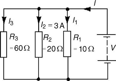
Figure 3.12 : Circuit for Example 3.8
Solution
(a) Voltage across 20 Ω resistor =I2R2 = 3×20=60 V; hence, supply voltage V=60 V since the circuit is connected in parallel.
Current I =I1 +I2 +I3 and hence, I = 6+3+1=10 A
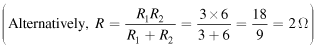
Alternatively, ![]()
Hence, total resistance ![]()
Example 3.9
Given four 1 Ω resistors, state how they must be connected to give an overall resistance of (a) 1/4 Ω (b) 1 Ω (c) ![]() (d)
(d) ![]()
Solution
(a) All four in parallel (see Figure 3.13),
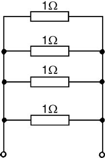
Figure 3.13 : Circuit for Example 3.9(a)9
Since ![]()
(b) Two in series, in parallel with another two in series (see Figure 3.14), since 1 Ω and 1 Ω in series gives 2 Ω, and 2 Ω in parallel with 2 Ω gives:
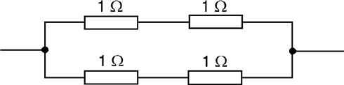
Figure 3.14 : Circuit for Example 3.9(b)9
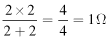
(c) Three in parallel, in series with one (see Figure 3.15), since for the three in parallel,
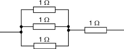
Figure 3.15 : Circuit for Example 3.9(c)9
![]() in series with 1 Ω gives
in series with 1 Ω gives ![]()
(d) Two in parallel, in series with two in series (see Figure 3.16), since for the two in parallel
Figure 3.16 : Circuit for Example 3.9(d)9
![]() and
and ![]() 1 Ω and 1 Ω in series gives
1 Ω and 1 Ω in series gives ![]()
Example 3.10
Find the equivalent resistance for the circuit shown in Figure 3.17.
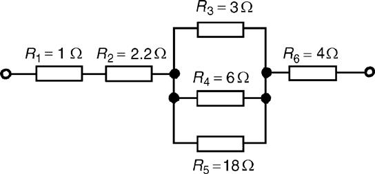
Figure 3.17 : Circuit for Example 3.10
Solution
R3, R4 and R5 are connected in parallel and their equivalent resistance R is given by:
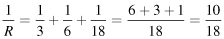
Hence, ![]()
The circuit is now equivalent to four resistors in series and the equivalent circuit resistance = 1+2.2+1.8+4=9 Ω.
Leave a Reply