
Determine suitable values for R1, R2, C1 and C2 for a second-order Butterworth filter with an upper cut-off frequency of 4 kHz and a pass-band gain of 20.
Solution
A problem of this nature requires a normalized response before it can be solved. The second-order Butterworth normalized response in this case will be given as:
![]() (17.9)
(17.9)
and the transfer function will be as stated previously in equation (17.8). If we multiply top and bottom of the right-hand side this equation by R1R2C1C2 and substitute K=20, we obtain:
![]() (17.10)
(17.10)
The next step is to equate the coefficients of equations (17.9) and (17.10): for the s2 terms
![]() (17.11)
(17.11)
and for the s terms:
![]() (17.12)
(17.12)
From (17.11) we may write:

as this will satisfy the right-hand side of the equation. Substituting in (17.12) will give:
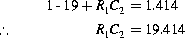
Letting R1=1 Ω gives C2=19.414 F. Since R2C2=1, we have R2=1/19.414=0.052 Ω. Finally R1C1=1, hence, C1=1F. We now have all the values which will enable us to build the filter, but remember these are normalized values and they have to be denormalized. The method of doing this is shown below.
We will assume a denormalization factor of 104. Note that 103 or 105 could have been used: this is purely arbitrary. Then:
![]() (17.13)
(17.13)
Similarly,
![]() (17.14)
(17.14)
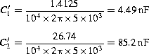
The capacitors are treated in a different way, but all you need to know is that the normalized values are divided by the cut-off frequency and the denormalization factor 104 as before:
![]() (17.15)
(17.15)
![]() (17.16)
(17.16)
The filter can now be built using the Sallen-Key circuit in Figure 17.16.
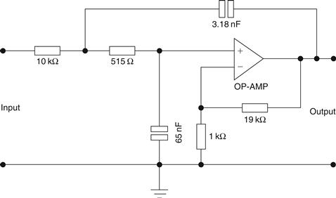
Figure 17.16 Sallen-Key circuit for Example 17.3
Example 17.4
Design the same filter as in Example 17.3, but with a Chebyshev response given by the following normalized transfer function.
Solution
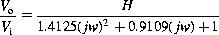
Once again using the procedure adopted in the previous example and equating the coefficients,
Denormalizing these values as before gives:
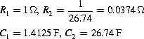
Also, ![]() and
and ![]() . The circuit is shown in Figure 17.17.
. The circuit is shown in Figure 17.17.

Figure 17.17 Circuit for Example 17.4
Leave a Reply