We have read that robot is a programmable machine that can complete a task. Correspondingly, the term robotics is the study focused on designing, developing and programming physical robots which are able to interact with the physical world and automate one or more tasks. Each robot has a different level of autonomy varying from human-controlled bots that carry out tasks to fully-autonomous bots that perform tasks without any external influences.
8.3.1 Artificially Intelligent Robot
Many people think that AI and robotics are synonymous. But this is not true. Table 8.1 highlights the difference between an AI program and a robot system.
TABLE 8.1 Difference between AI Program and Robot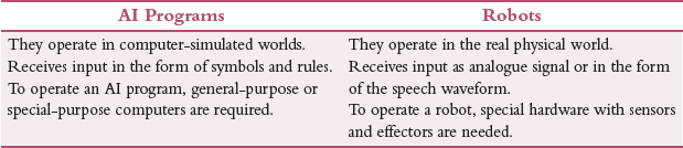
Moreover, from the Venn diagram as shown in Fig. 8.8, it is clear that there is one small area where the two fields overlap and, in this area, we have artificially intelligent robots (AIRs). These AIRs are the bridge between robotics and AI.
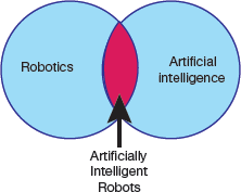
FIGURE 8.8 Venn diagram depiction relationship between AI and Robotics

Credit: PaO_STUDIO / Shutterstock
Although many AIRs (refer Fig. 8.9) are controlled by AI programs, they are not artificially intelligent. For example, most industrial robots are programmed to carry out a repetitive series of movements which do not require artificial intelligence. However, such non-intelligent robots have limited functionality.
To perform complex tasks, an artificially intelligent robot must implement some AI algorithm(s). For example, consider the scenarios given below to understand how AI can guide the functionality of a robot.
Case 1: A warehousing robot may use a path-finding algorithm to navigate around the warehouse.
Case 2: A drone may use autonomous navigation to return to its owner when it is about to run out of batteries.
Case 3: A self-driving car uses AI techniques to detect and avoid potential hazards on the road.
8.3.2 Characteristics of Robots
A robot is a mechanical device which completes it tasks in the environment for which it is designed. For example, the Mars 2020 Rover’s wheels are motorized and made of titanium tubing to firmly grip the harsh terrain of the red planet.
- Robots need electrical components that control and power the machinery. Usually, they draw electric current using a battery.
- Robots work on instructions written using computer programming. These instructions tell the robot what to do, when to do and how to do it.
8.3.3 Types of Robots
Mechanical bots come in a variety of designs, shapes and sizes to efficiently perform the task they are designed to perform. For example, RoboBee is a 0.2-millimeter-long robot while Vindskip is a 200-metre-long robotic shipping vessel. To classify them broadly into different categories, robots can be divided based on their capabilities to perform a particular task.
Pre-Programmed Robots
They operate in a controlled environment where they perform simple, monotonous tasks. For example, a mechanical arm on an automotive assembly line to weld a door on, to insert a certain part into the engine, etc. (as shown in Fig. 8.10) is an example of such a robot that performs its tasks faster and more efficiently than a human.

Credit: Pop Nukoonrat / 123RF
FIGURE 8.10 Pre-Programmed Robots
Humanoid Robots
They look like or mimic human behaviour and usually perform human-like activities (like walking, carrying objects). These days, humanoids look like us. For example, Hanson Robotics’ Sophia and Boston Dynamics’ Atlas.
Autonomous Robots
These machines operate independently of human operators and are usually designed to perform tasks in open environments without any human supervision. Autonomous robots perceive the world around them using sensors and then use decision-making capabilities to take the optimal next step based on their data and mission. For example, Roomba vacuum cleaner uses sensors to roam freely throughout a home. Other examples of autonomous robots are lawn trimming bots, hospitality bots, autonomous drones and medical assistant bots.
Most industrial robots are non-intelligent.
We often call these robots, cobots. Cobot, or a simple collaborative robot, is a non-intelligent robot. For example, a cobot can be programmed to pick up an object and place it elsewhere. This is done by training a specialized computer vision program to identify different types of objects generally by using an AI algorithm called Template Matching. Broadly, this is an autonomous function as no human intervention is required once the cobot has been programmed to do its task efficiently. Moreover, the task does not require any intelligence as the cobot will always be picking the object in the same way until its instructions are not changed.
Teleoperated Robots
These are semi-autonomous bots that use a wireless network to enable human control from a safe distance (as shown in Fig. 8.11). They are usually deployed in extreme geographical conditions, weather and circumstances. For example, drones used to detect landmines on a battlefield, robots used to fix underwater pipe leaks during oil spill are examples of teleoperated robots.

Credit: MONOPOLY919 / Shutterstock
FIGURE 8.11 Teleoperated Robots
Augmenting Robots
Also known as VR robots, they are used to enhance or replace current human capabilities. With their help, science fiction could become a reality very soon by making humans faster and stronger. For example, robotic prosthetic limbs or exoskeletons are used to lift hefty weights.
8.3.4 Types of Robots Based on Degree of Human Control
Independent Robots
They perform their work autonomously and independent of human operator control. So, they need to be intensely programmed. Such robots are deployed to replace humans for performing dangerous, mundane or otherwise impossible tasks ranging from bomb diffusion and deep-sea travel to factory automation. Though independent robots eliminate certain jobs, the also present new possibilities for growth.
Dependent Robots
These robots are non-autonomous robots as they interact with humans to perform their actions. Humans guide robots to enhance and supplement their already existing actions. For example, these days, advanced prosthetics (the branch of surgery concerned with the making and fitting of artificial body parts. For example, a piece of flexible material applied to a person’s face or body to change their appearance temporarily) are controlled by the human mind.
In 2018, Johns Hopkins APL created a popular example of a dependent robot was created by in 2018 for a patient (Johnny Matheny) whose arm was amputated above the elbow. A modular prosthetic limb was fitted in Matheny that was controlled by electromyography, or signals sent from his amputated limb that controls the prosthesis. Over time, he could accurately move his arm and even play the piano. At this time, the signals sent from his amputated limb became smaller and less variable.
Chatbots
Software robotics, also called bots, are computer programs that perform tasks autonomously. For example, a chatbot is a computer program that simulates conversation both online and over the phone and is often used in customer service scenarios. While simple chatbots answer questions with an automated response, more complex digital assistants learn from user information.
Robotics involves building robots physical whereas AI involves programming intelligence.
Types of Bots
Bots, or software robots only exist on the Internet and originate within a computer. Hence, they cannot be called robots. We have learnt in the characteristics of a robot that a robot has a physical form, such as a body or a chassis. Some popularly used bots are as follows:
- Chatbots carry out simple conversations to provide 24 X 7 customer service.
- Spam bots collect email addresses and send spam mail.
- Download bots automatically download software and apps.
- Search engine crawler bots scan websites and make them visible on search engines.
- Monitoring bots collect statistics to report speed and status of the website.
8.3.5 Components of a Robot
Robots are created to perform a variety of tasks to present a solution for a wide range of problems. For this, they need a set of specialized components that are discussed below.
Control System
Control system is a CPU that directs a robot’s task at high level. It performs all computations to tell a robot how to utilize its specific components, like how our brain sends signals to other parts of the body to complete a specific task. The tasks that a robot completes vary from an invasive surgery to assembly line packing.
Sensors
Sensors are devices that detect the events or changes in the environment and send data to the computer processor. For this, they are equipped with other electronic devices to provide electrical signals that allows the robot to interact with the world. Basically, the electrical signals act as a stimulus that are processed by the controller. Based on the stimulus received, the controller instructs the robot to interact with the outside world. This helps the robot to efficiently respond to real-time data. Popularly used sensors within a robot include video cameras (as eyes), photoresistors (react to light) and microphones (as ears). All these sensors allow the robot to capture information about its surroundings and process it to deduce the most logical conclusion and give commands to other components.
Robots are programmable, autonomous or semi-autonomous machines.
It is through these sensors that the robots get the ability to see, hear, touch and move like humans. Sensors are devices or machines which help to detect the events or changes in the environment and send data to the computer processor. These devices are usually equipped with other electronic devices. Similar to human organs, the electrical sensor also plays a crucial role in artificial intelligence and robotics. AI algorithms control robots by sensing the environment, and provide real-time information to computer processors.
Actuators
Actuators are the motor parts that facilitate a robot’s movement. We have read that a machine is a robot if it has a movable frame or body and actuators are the components that cause movement. Actuators are made up of motors that receive signals from the control system and move in tandem to carry out the movement necessary to complete the assigned task. They are made of metal or elastic.
Electric motors are the devices that convert electrical energy into mechanical energy and are required for the rotational motion of the machines.
Actuators help in moving and controlling a robot by using energy that can be electrical, hydraulic and air, etc. This means that actuators are usually operated using electricity (electrical), compressed air (pneumatic actuators) or oil (hydraulic actuators). Actuators can create linear as well as rotary motion.
Power Supply
Power supply is done to the robot by a battery. Just as we need food to do our work, robots require power to operate. The main use of power supply is to convert electrical current to power the load. Stationary robots used in a factory work on AC power while others operate via an internal battery.
While a majority of robots work on lead-acid batteries as they are safe and have long shelf life, others use compact and expensive silver-cadmium batteries. These batteries are chosen depending on safety, weight, replaceability and lifecycle of the robot.
AI algorithms are used in Google searches, Amazon’s recommendation engine and GPS route finders.
However, for future robotic development, pneumatic power from compressed gasses, solar power, hydraulic power, flywheel energy storage, organic garbage through anaerobic digestion and nuclear power are also being considered as potential sources of power.
Example of a pure AI is AlphaGo.
Pure AI is usually found in games. For example, in 1997, AI Deep Blue could easily defeat world champion. A more recent example is AlphaGo which won Lee Sedol, the world champion Go player, in 2016.
End Effectors
End effectors are the physical, typically external components of a robot that facilitate it to complete a task. For example, in factories, robots usually have interchangeable tools like paint sprayers, gripping claws or even hands for undertaking tasks like deliveries, packing, bomb diffusion, etc.
All these components are central to every robot’s construction.
8.3.6 AI Technology Used in Robotics
In this section, we will list AI technologies that are used in robotics. We have already studied some of them. These technologies are discussed below.
- Computer Vision: As studied earlier, Computer Vision is an important domain of artificial intelligence that extracts useful information from images, videos and visual inputs to perform appropriate action(s).
- Natural Language Processing (NLP): NLP is used to give voice commands to AI robots to create a strong human-robot interaction. NLP helps the robot to understand and reproduce human language. Besides recognizing human language, robots can learn the accent, and predict how humans speak.
- Edge Computing: Edge computing in robots helps in robot integration, testing, design and simulation to provide better data management, lower connectivity cost, better security practices, more reliable and uninterrupted connection.
- Complex Event Process: An event is said to occur when there is a change of state and one or more events combine to define a complex event. Correspondingly, complex event processing (CEP) helps us to understand the processing of multiple events in real time.The term ‘complex event process’ is popularly used in various industries including healthcare, finance, security, marketing, detecting credit card fraud, stock marketing, etc. For example, the deployment of an airbag in a car is a complex event that is based on real-time data coming from multiple sensors.
- Transfer Learning and AI: Transfer learning solves a problem with the help of an already solved problem. So, the knowledge gained from solving one problem is utilized to solve another problem that is related to the problem to be solved. For example, the model used to recognize a square shape can also be used to identify a circular shape.Since transfer learning reuses the pre-trained model for a related problem, the actual learning time for the new problem to be solved is relatively less and thus provides a cheaper solution. In robotics, transfer learning trains one machine using other machines.
- Reinforcement Learning: Reinforcement learning focuses on learning based on feedback. In this technique, an AI agent to learns and explores the environment, performs actions and automatically learns from experience or feedback obtained for each action. Reinforcement learning makes the agent learn to behave optimally through hit-and-trail method while interacting with the environment. It is mainly used to deduce decisions to achieve goals in an uncertain and potentially complex environment.In the context of robotics, robots explore the environment to learn how to work optimally through hit and trial method. For every correct action, the robot gets a reward and a punishment for an incorrect action. In this way, reinforcement learning provides a framework to design and simulate sophisticated and hard-to-engineer robotic behaviours.
- Affective computing: Affective computing focuses on developing systems that can identify, interpret, process and simulate human emotions. Therefore, this study aims to imbibe emotional intelligence in robots so that they are able to observe interpret and express themselves emotionally.
- Mixed Reality: Mixed reality is an emerging field that focuses on programming by demonstration (PbD). PbD creates a prototype using a combination of physical and virtual objects.
8.3.7 Planning and Navigation
In this section, we will read about mobile robots that are critical to robust mobility. For this we must have some knowledge about the kinematics of locomotion, sensors for determining the robot’s environmental context and techniques for localizing with respect to its map. Here, we will talk about cognitive level of robots.
Cognition refers to the capability of a system to make purposeful decision and execute them to achieve its highest-order goals. In the context of a mobile robot, cognition refers to robust mobility. Robot navigation aims to make the robot reach its goal position efficiently and reliably based on its knowledge about its environment, the goal position and values of the sensor.
Although many different approaches have been proposed for navigating a robot, there are strong similarities between all of them. The underlying difference exists in the manner in which they decompose the problem into smaller sub-units. Given a map and a goal location, path planning identifies a trajectory that will help the robot to reach the final destination.
8.3.7.1 Competencies for Planning—Planning and Reacting
Path planning is a strategic problem-solving competency (capability), as the robot must make vital decisions to achieve its goals. The second competency is tactical extreme to avoid all obstacles and collisions by modulating the trajectory of the robot. Given readings of real-time sensor readings, several approaches are proposed to avoid obstacles. We will discover a few of them.
While navigating, a robot plans and reacts. Without reacting, the planning effort(s) will be of no use as the robot never be able to reach its goal. Correspondingly, without planning, the robot will never reach its goal.
Suppose a robot R at time i in the initial belief state bi has a map Mi to reach position p while satisfying certain some temporal constraints locg(R) = p; (g ≤ n) (like before timestep n).
Although the robot’s movements have to be physical, the robot can only sense its belief state, not its physical location. We will, therefore, map the goal of reaching location p to reaching a belief state bg. We need a plan q that specifies one or more trajectories from bi to bg.
However, the problem arises when either the robot’s position is not quite consistent with bi or Mi is incorrect and/or incomplete. Furthermore, the real-world environment is dynamic. Even if Mi is correct at time i, M may change over time as the robot must incorporate new information gained during plan execution.
Over a period of time, the environment changes and the robot’s sensors gather new information. In this scenario, reacting becomes more important. Reacting modulates the robot’s behaviour to update the planned upon trajectory so that the robot still reaches its goal position. Moreover, unanticipated new information also requires changes to the robot’s strategic plans. Therefore, in the specified time limits, the plan should consider every new piece of information in real time to produce a new plan to react to the new information appropriately. This theoretical extreme, the point at which the concept of planning and reacting merge, is called integrated planning and execution.
8.3.7.2 Key Terms in Trajectory Planning
Trajectory Planning
Trajectory planning refers to moving from point A to point B while avoiding collisions over time in a 2D or 3D space (refer Fig. 8.12). It is an important concept in designing autonomous vehicles. Trajectory planning also known as motion planning is mistakenly referred to as path planning. However, it is different from path planning as it is parametrized by time. Besides path planning, trajectory planning also incorporates planning based on velocity, time, and kinematics.
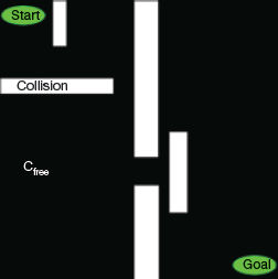
FIGURE 8.12 Trajectory planning
Configuration Space
A configuration is the pose of a robot describing its position. Correspondingly, Configuration Space C, is the set of all configurations. For example, in a 2D space, a robot’s configuration is given by coordinates (x, y) and angle θ. Similarly, in 3D space, a robot’s configuration is given by coordinates (x, y, z) and angles (α, β, γ).
The goal of path planning is to find a path from the initial position to the goal position in the physical space that avoids all collisions with the obstacles. This problem becomes particularly more difficult as k grows large. If we define the configuration space obstacle O as the subspace of C, the free space in which the robot can move safely can be computed as, F = C – O.
Figure 8.13 shows a picture of the physical space and a 2D configuration space for a planar robot arm with two links. The robot’s goal is to move its end effector from position c1 to c2.
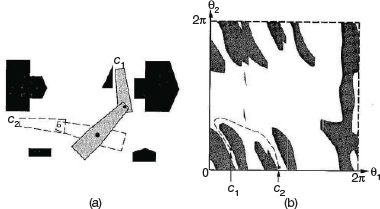
FIGURE 8.13 Physical space and a 2D configuration space
Free Space
Free space Cfree is the set of all configurations that are collision-free. The robot should be programmed to use kinematics and collision detection from sensors to ensure if a given configuration is a collision free or not.
Target Space
Target space is a linear subspace of free space and consists of space in which we want the robot to explore. In global motion planning, target space is observable by the robot’s sensors. But in local motion planning, some states in target space are not observable by robot’s sensors. To solve a problem, robots assume several observable virtual target spaces (around itself). The virtual target space is often referred to as sub-goal.
Degrees of Freedom
It specifies modes in which a mechanical device or system can move. This means that the number of degrees of freedom is equal to the total number of independent displacements or aspects of motion. For example, in a robotic arm, shoulder and wrist can move up or down, left or right but elbow can move up or down. Wrist and shoulder can also be rotated (or rolled).
Therefore, such a robot arm has five to seven degrees of freedom. And if the robot has two arms, then total number of degrees of freedom is doubled.
Multi-legged mobile robots can have more than 20 degrees of freedom. For example, Project Nao, which looks superficially like a large space-age doll, has 25 degrees of freedom.
8.3.7.3 Problem Constraints in Trajectory Planning
Trajectory planning suffers from two main problems which are discussed below.
Holonomicity
This gives the relationship between the controllable degrees of freedom and total degrees of freedom of the robot. A robot is said to be holonomic if the number of controllable degrees of freedom is greater than or equal to the total degrees of freedom. Holonomic robots are easy to work with as they facilitate many movements easier to make. Moreover, returning to a past pose is much easier.
For example, if a self-driving car is designed as a non-holonomic robot, then it will have no way to move laterally, thereby making its certain movements (like parallel parking) difficult. In contrast to this, a holonomic vehicle would be one with mecanum wheels, such as the new Segway RMP.
Dynamic Environments
In dynamic environments, like the real world, objects that may cause collision are not stationary. This makes trajectory planning more difficult as objects are moving with respect to time. Many-a-time, it may not be possible for a robot to move backward in time. Moreover, many choices are completely irreversible due to terrain, such as moving off of a cliff.
8.3.7.4 Planning Algorithms
In this section, we will discuss three types of planning algorithms.
- Artificial Potential Field: The algorithm places values over the map with the goal having the lowest or highest value that either increases or decreases depending on the distance from the goal (refer Fig. 8.14).
 FIGURE 8.14 Artificial Potential FieldObstacles defined can have an incredibly high or low value. The robot is programmed to move to the lowest or (highest) potential value adjacent to it, which should lead it to the goal. However, this algorithm often gets trapped in local minima.
 - Sampling-based Planning: Roadmap method is an example of sampling-based planning method. The algorithm first selects a sample of N configurations in C as milestones. Then, a line PQ is formed between all milestones as long as the line PQ is completely in Cfree. Following this, any graph search algorithms can be used to find a path from start to the goal. Though a large number of N increases computation time, it results in better solutions.
- Grid-based Planning: This algorithm overlays a grid on the map (as shown in Fig. 8.15) and then ensures that every configuration corresponds with a grid pixel. The robot can move from one grid pixel to another adjacent grid pixel if that grid pixel is in Cfree. T
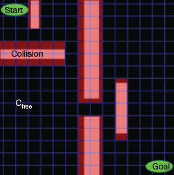 FIGURE 8.15 Grid-based PlanningSearch algorithm like A
 is used to find a path to reach the goal position from the starting position. Although a lower resolution grid having bigger pixels will make the search procedure execute faster, it may however miss paths through narrow spaces of Cfree. Moreover, as the resolution of the grid increases, memory usage also grows exponentially. In such a scenario and especially in large areas, another path planning algorithm may be necessary.
 - Reward-based Planning: Algorithms based on research-based planning assume that robot in each state (position) may select any action (regarding motion). However, the result of each action is not definite. In such a case, outcomes or displacement, in this context, are partly random and partly under the robot’s control. On reaching the goal, the robot gets a positive reward and a negative reward on colliding with an obstacle.Research-based planning algorithms, therefore, aim to find a path giving maximum future rewards. Markov decision processes (MDPs) is a popular technique used in many of reward-based algorithms. Though this technique generates optimal path, this path may not be smooth as it limits the robot to choose from a finite set of actions. To overcome this drawback, usually Fuzzy Markov decision processes (FDMPs), an extension of MDPs, is used to generate a smooth path with using a fuzzy inference system.
- Road-map Path Planning: Road-map path planning algorithms capture the connectivity of the robot’s free space in a network of one-dimensional curves or lines, called road-maps. Once a road-map is constructed, it is then used to plan a robot’s motion. The algorithm reduces the problem of path planning to connecting the initial and goal positions of the robot to the road network and then searching the roads from the initial position to the goal position of the robot. This means that, road-map uses the obstacle’s geometry to decompose the robot’s configuration space.
The challenge is to construct a set of roads that together helps the robot to move around anywhere in its free space, while minimizing the number of total roads. In this section, we will discuss two approaches for road mapping—visibility graph and Voronoi diagram. While visibility graph finds paths that have minimum lengths by bringing the roads closer to the obstacles, Voronoid diagram, on the other hand, keeps roads as far as possible from the obstacles.
8.3.7.5 Visibility Graph
The visibility graph for a polygonal configuration space C includes all edges (including initial and final positions) joining every pair of vertices that can see each other. The unobstructed roads depicted as straight lines in the graph are the shortest distances between two vertices. The job of the path planning algorithm is to find the shortest path from the initial position to the goal position along the roads drawn in the visibility graph (see Fig. 8.16).
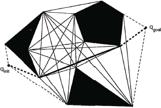
The visibility graph path planning algorithm is very simple and straight-forward. It can be readily used when objects in the environment are described as polygons either in continuous or in discrete space. However, there are two important limitations of this algorithm.
First, with increase in the number of obstacle polygons, the number of edges and vertices increases. Therefore, this algorithm works well in sparse environments, but is very slow and inefficient when used in densely populated environments.
Second, the solution paths found by visibility graph planning algorithm takes the robot as close as possible to obstacles on the way to the goal.
Though this algorithm is optimal in terms of the length of the solution path, it does not keep the robot away from obstacles. This compromises safety. A potential solution can be either to grow the obstacle’s size significantly so that it becomes more than the robot’s radius, or modify the solution path after path planning to distance the path from obstacles. However, such fixes compromise the optimal-length results of the algorithm.
8.3.7.6 Voronoi Diagram
A Voronoi diagram maximizes the distance between the robot and obstacles in the map. For each point in the free space, distance from that point to the nearest obstacle is calculated and plotted as a height coming out of the page (refer to Fig. 8.17). As the robot moves away from the obstacle, the height increases. Sharp ridges can be seen in the Voronoi diagram at points that are equidistant from two or more obstacles. Edges are formed by these sharp ridge points. When obstacles in the configuration space are polygons, the Voronoi diagram has straight and parabolic segments as shown in Fig. 8.18.
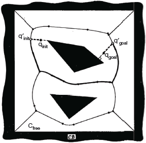
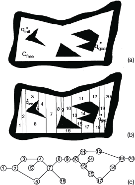
FIGURE 8.18 Forming Edges and making graph from the given Vornoi Diagram
The path in the Voronoi diagram may not be optimal in terms of total path length. Another limitation of this diagram is limited range localization sensors. Since the distance between the robot and obstacle is maximized, any short-range sensor on the robot may not be able to sense its surroundings. Hence, the chosen path may be quite poor from a localization point of view.
However, the main reason of popularity of the Voronoi diagram method is its executability. Given a planned path via Voronoi diagram planning, a robot with range sensors can follow a Voronoi edge in the physical world using simple control rules that match those used to create the Voronoi diagram. Voronoi Diagram can also be used to conduct automatic mapping of an environment by finding and moving on unknown Voronoi edges and creating a consistent Voronoi map of the environment.
8.3.7.7 Cell Decomposition Path Planning
The cell decomposition path planning aims to distinguish between geometric areas, or cells, that are free and areas that are occupied by objects. The following must be kept in mind.
- The graph is divided into simple, connected regions called ‘cells’.
- A connectivity graph is constructed by identifying opens cells that are adjacent.
- Identify the cells in which the initial and goal configurations lie. Select a path in the connectivity graph that joins the initial and the goal cell.
- From the cells identified, compute a path within each cell following motions and movements along straight lines.
The most important concept in cell decomposition method is the placement of the boundaries between cells. There are two methods which perform the task.
- Exact cell decomposition: In this technique, the boundaries are placed as a function of the structure of the environment in such a way that the decomposition is lossless.
- Approximate cell decomposition: This approach performs decomposition as an approximation of the actual map.
8.3.7.8 Exact Cell Decomposition
In Fig. 8.19, exact cell decomposition has been used. Here, the boundary of cells is based on geometric criticality. So, the resulting cells are either completely free or completely occupied resulting in a complete path. In this method, the robot’s ability to traverse from each free cell to adjacent free cells is more important than the position of the robot within each cell of free space.
Advantage
In environments that are extremely sparse, the number of cells will be small.
Disadvantages
- The number of cells and computational efficiency of the overall path planning algorithm depends upon the density and complexity of objects in the environment.
- Due to complexities in implementation, the exact cell decomposition technique is less frequently used in mobile robot applications.
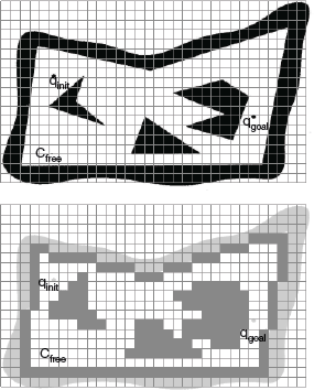
FIGURE 8.19 Exact Cell Decomposition
8.3.7.9 Approximate Cell Decomposition
Approximate cell decomposition is a popular technique for mobile robot path planning. It uses grid-based environmental representations that are themselves fixed gridsize decompositions. They are quite similar to an approximate cell decomposition of the environment.
We can see that in Fig. 8.20, the cell size is not dependent on the particular objects in an environment resulting in loss of narrow passageways due to the inexact nature of the tessellation. However, this is rarely a problem as the cell size used is very small, usually 5 cm on each side.
The main advantage of fixed-size cell decomposition is the low computational complexity of path planning. In Fig. 8.20, we see that the free space is externally bounded by a rectangle which is further decomposed into four identical rectangles. The rectangle is not decomposed further only in two conditions.
- First, the interior of a rectangle lies completely in free space.
- Second, the interior of a rectangle lies completely in the configuration space obstacle.
If the two conditions are not satisfied, then the rectangle is recursively decomposed into four rectangles until one of them is met. Note that the white cells lie outside the obstacles, the black inside and the grey are part of both the regions.
This technique is an efficient and simple strategy for finding routes in fixed-size cell arrays. The algorithm starts from the goal position marking for each cell its distance to the goal cell until the initial robot position is reached. At this point, distance to the goal position and a specific solution trajectory is known by linking together cells that are adjacent and closer to the goal.
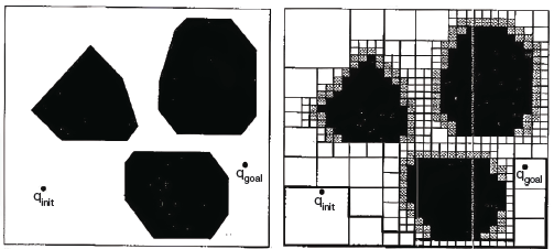
FIGURE 8.20 Approximate Cell Decomposition
If the entire array is in memory, then each cell is visited only once to deduce the shortest path from the initial position to the goal position. So, the search is linear. Therefore, the complexity of this algorithm neither depends on the sparseness and density of the environment, nor on the complexity of the objects’ shapes in the environment.
The Cye robot is an example of a commercially available robot that plans path in a 2D space with 2 cm fixed-cell decomposition of the environment. Unlike exact cell decomposition method, approximate cell decomposition method does not guarantee completeness but it is mathematically less involving and easier to implement.
8.3.7.10 Potential Field Path Planning
Potential field path planning algorithm creates a field across the robot’s map that directs the robot to the goal position. The potential field technique considers robot as a point under the influence of an artificial potential field U(q).
Like a ball roll downhill under a gravitational field, the robot moves by following the potential field. The goal acts as an attractive force on the robot and the obstacles act as peaks, or repulsive forces. The superposition of all forces is applied to the robot. The artificial potential field thus created helps the robot to avoid known obstacles and smoothly move towards the goal. Thus, this concept goes beyond path planning.
Basically, the resulting field is a control law for the robot. A robot can always decide its next action, assuming that it can localize its position based on the map and potential field.
Knowing that the robot is attracted towards the goal and repulsed by the known obstacle, we need to update the potential field as soon as a new obstacle appear during robot motion. Considering robot as a point, the robot’s orientation θ is neglected and the resulting potential field is only two dimensional (x,y).
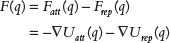
Assuming a differentiable potential field function U(q), related artificial force F(q) acting at the position (x,y) is calculated as follows:

where ΔU(q) is the gradient vector of U at position q.

The potential field acting on the robot is then computed as the sum of the attractive field of the goal and the repulsive fields of the obstacles. Thus,
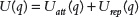
Correspondingly, the net force after considering attracting and repulsing forces is calculated as,
Leave a Reply